


1. INTRODUCTION
1.1 Gree
�
ng
Thank you for choosing the BDM-600 micro inverter from NEP. This product will
maximize your inversion bene
fi
t with the minimal amount of design and
installa
�
on complexity. This document should provide you with all of the
necessary steps to correctly install the NEP-600 dual module microinverter in
sites located in North America. However, should you have addi
�
onal ques
�
ons
please contact NEP’s technical representa
�
ve at [email protected].
1.2 System Compa
�
bility
The BDM-600 is designed to support either one or two 60 or 72 cell modules in
grid-
�
ed PV system consists of PV panels, grid-
�
ed inverter and junc
�
on boxes.
The DC output from the PV panels is converted into AC energy and fed back to
the grid through the BDM-600. The BDM-600 also provides e
ff
ec
�
ve
an
�
-islanding isola
�
on between the PV module and AC grid output.
1.3 How to Use This Manual
This manual provides detailed product informa
�
on and installa
�
on instruc
�
ons
for the BDM-600 micro solar inverter. Please read through this manual before
installa
�
on and opera
�
on.
WARNING
:
This indicates a situa
�
on where failure to follow instruc
�
ons
may be a safety hazard or cause equipment malfunc
�
on. Use extreme cau
�
on
and follow instruc
�
ons carefully.
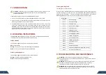
1.4 Label
A label is located on the side of the inverter which includes technical data as well
as type and serial number of the device. Safety instruc
�
ons are listed and
explained below:
Danger!
The term “danger” describes an issue which, if ignored can cause
personal injury.
A
�
en
�
on!
With the term “a
�
en
�
on” a circumstance is listed which may
cause property damage if disregarded.
Instruc
�
ons for use!
Under “Instruc
�
ons for Use“, it is pointed out that installa
�
on and
opera
�
ng instruc
�
ons are to be read and understood before
installa
�
on or repair.
Cau
�
on, hot surface!
Under “Cau
�
on, hot surface”, it should be noted that surfaces of
equipment may be hot and create a burn hazard.
Special disposal instruc
�
ons!
With “Note Separate Disposal”, it is pointed out that this product
may not be disposed of with normal garbage. An improperly
conducted disposal can lead to damage to the environment.
ETL Cer
�fi
ca
�
on
This marks cer
�fi
es that the product complies with all relevant
UL requirements for sale in North America.
2. SAFETY INSTRUCTION
WARNING:
PLEASE READ THIS MANUAL PRIOR TO INSTALLATION. PRODUCT DAMAGE RESULTING FROM FAILURE TO
FOLLOW THIS MANUAL IS NOT COVERED BY THE WARRANTEE.
INSTALLATIONS SHOULD BE DONE ONLY BY CERTIFIED ELECTRICIANS.
NOTHING INSIDE THE INVERTER SHOULD BE MODIFIED
ONLY NEP APPROVED CABLING SHOULD BE USED TO CONNECT MICROINVERTERS
ALL INSTALLATIONS SHOULD FOLLOW THE LOCAL ELECTRICAL CODES. ADDITIONAL PROTECTION FOR THE AC
WIRING FROM THE INVERTERS SHOULD BE PROVIDED AND MAY BE REQUIRED BY LOCAL AND NATIONAL WIRING
REGULATIONS. THIS PROTECTION IS LIKELY TO INCLUDE RESIDUAL CURRENT DEVICES, EARTH FAULT MONITORS
AND CIRCUIT BREAKERS. THIS PRODUCT MAY CAUSE AC CURRENT WITH A DC COMPONENT. IF A RESIDUAL
CURRENT-OPERATED PROTECTIVE DEVICE (RCD) OR A MONITORING DEVICE (RCM) IS USED FOR PROTECTION IN
CASE OF DIRECT OR INDIRECT CONTACT, ONLY AN RCD OR RCM OF TYPE B IS ALLOWED ON THE AC SIDE OF THIS
PRODUCT
.
NEVER DISCONNECT THE PV MODULES FROM THE MICRO-INVERTER WITHOUT FIRST ISOLATING THE AC MAINS.
ALL PV AND AC CONNECTORS ARE NOT TO BE DISCONNECTED UNDER LOAD. THE AC BRANCH CIRCUIT BREAKERS
MUST BE FIRST SWITCHED OFF.
PLEASE CONTACT AUTHORIZED SERVICE AGENTS FOR ANY SERVICE WORK.
BDM-600 IS A GRID-TIED SOLAR INVERTER. IT MAY REQUIRE APPROVAL FROM THE LOCAL UTILITY COMPANY
PRIOR TO CONNECTION TO THE POWER GRID.
THE BDM-600 DOES NOT INCLUDE ANY USER SERVICABLE COMPONENTS.
WARNING:
THE PV ARRAY SUPPLIES A DC VOLTAGE TO THE MICROINVERTER WHEN EXPOSED TO
LIGHT.
3. FCC COMPLIANCE
This equipment has been tested and found to comply with the limits for a Class B digital
device, pursuant to part 15 of the FCC Rules. These limits are designed to provide reasonable
protec
�
on against harmful interference in a residen
�
al installa
�
on. This equipment generates
uses and can radiate radio frequency energy and, if not installed and used in accordance with
the instruc
�
ons, may cause harmful interference to radio communica
�
ons. However, there is
no guarantee that interference will not occur in a par
�
cular installa
�
on. If this equipment
does cause harmful interference to radio or television recep
�
on, which can be determined by
turning the equipment o
ff
and on, the user is encouraged to try to correct the interference by
one or more of the following measures:
●
Reorient or relocate the receiving antenna.
●
Increase the separa
�
on between the equipment and the receiver.
●
Connect the equipment into an outlet on a circuit di
ff
erent from that to
which the receiver is connected.
●
Consult the dealer or an experienced radio/TV technician for help.
Changes or modi
fica�
ons not expressly approved by the party responsible for compliance may
void the user’s authority to operate the equipment.
02
03


