


CHAPTER 1. MMO-700
1.4. ARM
1.4 Arm
1.4.1 Properties of the Universal Robots Arms
The hardware of the UR robot arm has not been modified. All features and properties of the arm remain unchanged as
stated in the manufacturer’s documentation. Please refer to this documentation for further information.
The platform’s emergency stop system was integrated into the arm’s safety system as external machine. Technical
details on this connection can be found in the electrical circuit diagram of the MMO-700 UR and in the operating
manual of the robot arm. In case the arm is to be operated separately this connection has to be bridged with the white
connector -X32’ that was included in delivery.
Tip:
The configurable inputs CI0 and CI1 have been changed to “Unassigned”. The configurable outputs CO0 and
CO1 have been set to “Emergency stop”. The safety configuration password was set to
neobotix
. Please contact
Neobotix if you have any questions concerning the safety system.
1.4.2 Standalone Operation
The mobile platform can be operated without switching on the arm or completely without arm. To do so please plug in
the bridging connector -X32 instead of the cable to the UR arm controller. This connector can be found at the cables
from platform to cabinet at the right side of the platform’s top plate.
The robot arm can be operated independently of the mobile platform if the corresponding bridging connector -X32 is
connected to the cable leading to the controller box.
When operating the arm without the platform it is recommended to power it from an ordinary 230V power outlet and
not from the mobile robot’s integrated DC/AC inverter.
Please check the robot arm’s operating manual for details on the power requirements.
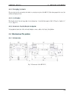
1.5 Mechanical Properties
1.5.1 Dimensions of the Robot
See
(page 13).
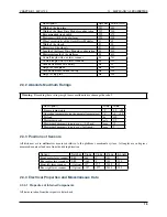
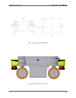
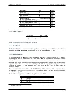
1.5.2 Dimensions of the Manipulator
All dimensions are in millimetres.
Description
Symbol
Value
Height of the mounting plane
H1
348
Height of the control cabinet’s top plate
H2
767
Offset between arm base and platform centre
O
161
Distance to the front of the cabinet
L1
115
Length of the cabinet’s top plate
L2
492
Width of the cabinet’s top plate
W
515
4