


CHAPTER 4. OMNI DRIVE MODULE
4.4. ELECTRICAL INSTALLATION
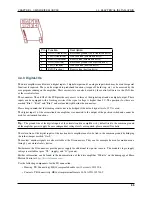
Pin
Function
Description
1
A+
Channel A of the TTL motor encoder, for motion monitoring
2
B+
Channel A of the TTL motor encoder, for motion monitoring
3
O-
Emitter contact of the optocoupler of digital output 1
4
G
Main ground
5
I-
Common ground of the digital inputs
6
I2
Digital input 2 (mind the limiting resistor)
7
A-
Channel A (inverted) of the TTL motor encoder, for motion monitoring
8
B-
Channel B (inverted) of the TTL motor encoder, for motion monitoring
9
O1
Collector contact of the optocoupler of digital output 1
10
VL
Logic supply (output)
11
I1
Digital input 1 (mind the limiting resistor)
12
I3
Digital input 3 (mind the limiting resistor)
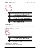
4.4.3.1 Motion Monitoring
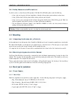
On request the connectors can be prepared to provide direct access to the encoder signals of the traction and / or
orientation motor from outside.
This option will change the pin assignment as follows.
Pin
Function
Description
1
O-
Emitter contact of the optocoupler of digital output 1
2
B+
Channel A of the TTL motor encoder, for motion monitoring
3
A+
Channel A of the TTL motor encoder, for motion monitoring
4
O1
Collector contact of the optocoupler of digital output 1
5
B-
Channel B (inverted) of the TTL motor encoder, for motion monitoring
6
A-
Channel A (inverted) of the TTL motor encoder, for motion monitoring
This option requires different connector housings:
TE Connectivity, HE14 receptacle double row 6 circuits, 281839-3
54