Section 8: Packing for Shipment
8-2
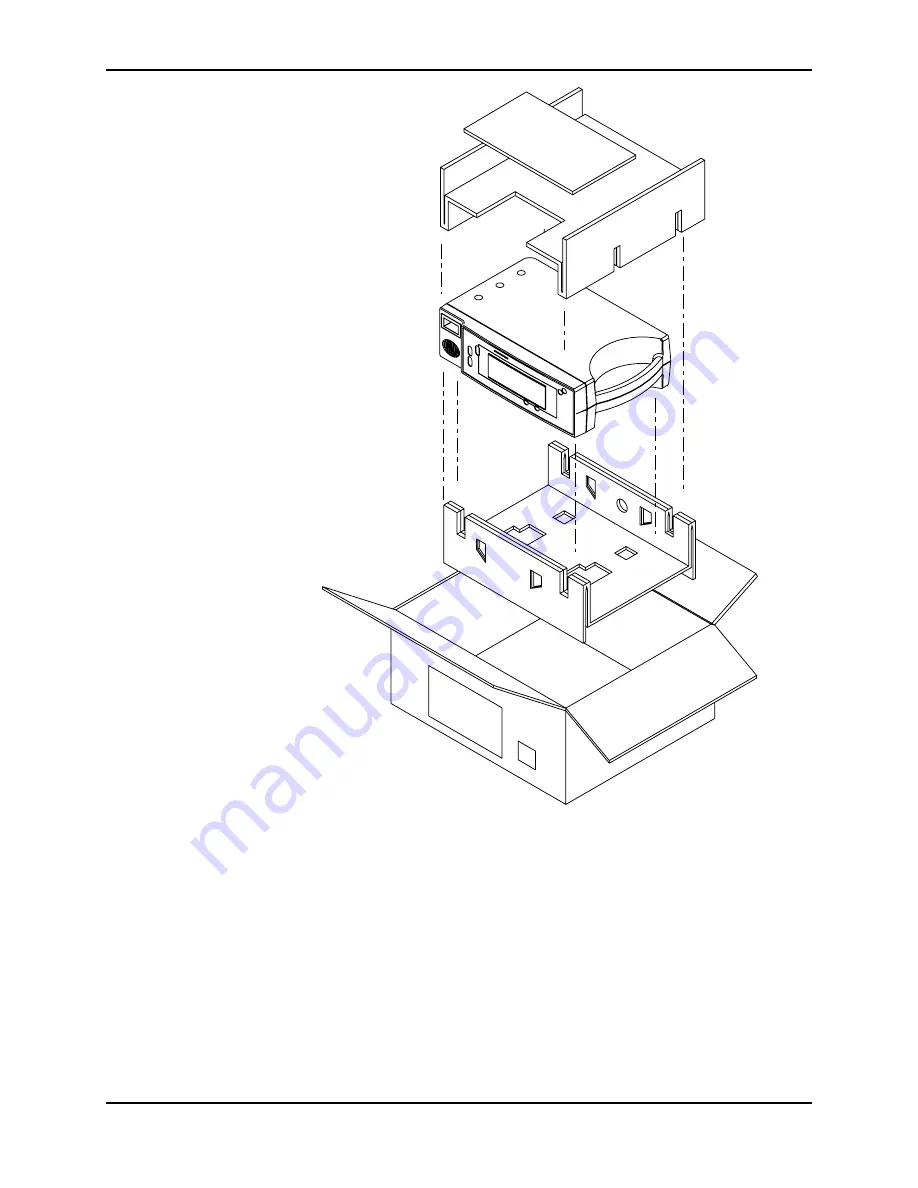
Figure 8-1: Repacking the NPB-190
2.
Place in shipping carton and seal carton with packaging tape.
3.
Label carton with shipping address, return address and RGA number.
Page 1: ... physician To contact Mallinckrodt s representative In the United States call 1 800 635 5267 or 314 654 2000 outside of the United States call your local Mallinckrodt representative 0123 1999 Mallinckrodt Inc All rights reserved 033925E 0599 SERVICE MANUAL NPB 190 Pulse Oximeter ...
Page 2: ...emarks of Mallinckrodt Inc To obtain information about a warranty if any for this product contact Mallinckrodt Technical Services or your local Mallinckrodt representative Purchase of this instrument confers no express or implied license under any Mallinckrodt patent to use the instrument with any sensor that is not manufactured or licensed by Mallinckrodt Durasensor and Oxisensor II are trademark...
Page 3: ...Settings 4 1 4 3 Service Menu 4 2 Section 5 Troubleshooting 5 1 5 1 Introduction 5 1 5 2 How To Use This Section 5 1 5 3 Who Should Perform Repairs 5 1 5 4 Replacement Level Supported 5 1 5 5 Obtaining Replacement Parts 5 1 5 6 Troubleshooting Guide 5 2 5 7 Error Codes 5 7 Section 6 Disassembly Guide 6 1 6 1 Introduction 6 1 6 2 Prior to Disassembly 6 1 6 3 Fuse Replacement 6 2 6 4 Monitor Disasse...
Page 4: ...ce 9 3 Appendix Serial Port Interface Protocol A 1 A1 Introduction A 1 A2 Enabling the Serial Port A 1 A3 Connecting to the Serial Port A 1 A4 Real Time Printout A 2 A5 Nurse Call A 5 Technical Supplement S 1 S1 Introduction S 1 S2 Oximetry Overview S 1 S3 Circuit Analysis S 3 S4 Functional Overview S 3 S5 AC Input S 3 S6 Power Supply PCB Theory of Operation S 4 S7 Battery S 5 S8 User Interface PC...
Page 5: ...eaker 6 12 Figure 7 1 NPB 190 Exploded View 7 2 Figure 8 1 Repacking the NPB 190 8 2 Figure A 1 Serial Port Pin Layout A 2 Figure A 2 Real Time Printout A 2 Figure S 1 Oxyhemoglobin Dissociation Curve S 2 Figure S 2 NPB 190 Functional Block Diagram S 3 Figure S 3 Front End Red IR Schematic Diagram S 11 Figure S 4 Front End LED Drive Schematic Diagram S 13 Figure S 5 Front End Output Schematic Diag...
Page 6: ... Patient Leakage Current Test Configurations Mains Voltage on the Applied Part 3 12 Table 4 1 Factory Default Settings 4 3 Table 5 1 Problem Categories 5 2 Table 5 2 Power Problems 5 3 Table 5 3 Button Problems 5 4 Table 5 4 Display Alarms Problems 5 4 Table 5 5 Operational Performance Problems 5 5 Table 5 6 Serial Port Problems 5 6 Table 5 7 Error Codes 5 7 Table A 1 Serial Port Pin Outs A 1 Tabl...
Page 7: ...or NPB 190 portable pulse oximeter is intended for continuous noninvasive measurement of functional oxygen saturation of arterial hemoglobin SpO2 and pulse rate measured by SpO2 sensor The monitor is intended for use on adult pediatric and neonatal patients in all hospital type facilities and in the home environment It may be used during intra hospital transport when powered by its internal batter...
Page 8: ...erminal 4 Fuse Drawer 2 AC Connector 5 Voltage Selector Switch 3 Serial Port 1 3 POWER ON SELF TEST When the NPB 190 is turned on it will perform a POST Power On Self Test During POST the following sequence should occur All indicator lights illuminate All segments of the numeric digits light All segments of the Pulse Amplitude Display light U S PATENTS 4 621 643 4 653 498 4 700 708 4 770 179 4 869...
Page 9: ...are often needed when calling Mallinckrodt s Technical Services Department or your local Mallinckrodt representative for technical assistance Record the numbers and have them available prior to requesting technical assistance Upon successful completion of POST the NPB 190 sounds a 1 second tone indicating that the monitor has passed the test If the start up sequence is not completed as described a...
Page 10: ......
Page 11: ...nspect the exterior of the NPB 190 for damage 2 Inspect safety labels for legibility If the labels are not legible contact Mallinckrodt s Technical Services Department or your local Mallinckrodt representative 3 Verify that the unit performs properly as described in paragraph 3 3 4 Perform the electrical safety tests detailed in paragraph 3 4 If the unit fails these electrical safety tests do not ...
Page 12: ......
Page 13: ...el 87 or equivalent Durasensor oxygen transducer DS 100A Oxisensor II oxygen transducer D 25 Pulse oximeter tester SRC 2 Safety analyzer Must meet current AAMI specifications Sensor extension cable EC 4 or EC 8 Serial interface cable EIA 232 cable optional Stopwatch Manual or electronic 3 3 PERFORMANCE TESTS The battery charge procedure should be performed before monitor repairs whenever possible ...
Page 14: ...Limit Ranges NPB 190 On Standby Alarm Silence Adjust Up Adjust Down Lower Alarm Limit Upper Alarm Limit Figure 3 1 NPB 190 Controls Note Refer to Figure 3 1 NPB 190 Controls when following the instructions listed below 3 3 2 1 Power On Self Test 1 Connect the monitor to an AC power source Verify that the AC Power Battery Charging indicator is lit 2 Do not connect any input cables to the monitor 3 ...
Page 15: ... each window 3 3 2 2 Factory Power On Defaults and Alarm Limit Ranges Note When observing or changing default limits a 3 second timeout is in effect that is if no action is taken within 3 seconds the monitor automatically returns to the normal mode 1 Turn the monitor on by pressing the Power On Standby button Wait for POST to be completed Press and release the Upper Alarm Limit button Verify that ...
Page 16: ...ting of 85 5 Press the Upper Alarm Limit button two times rapidly twice within 3 seconds Verify that the monitor emits two beeps the pulse rate display indicates an alarm limit of 170 and that the SpO2 display window shows three dashes at the top for about 3 seconds Figure 3 5 Adjusting High Heart Rate Alarm Limit 6 Press the Upper Alarm Limit button two times rapidly Press and hold the Adjust Dow...
Page 17: ...e testing include the following tests Operation with a Pulse Oximeter Tester General Operation 3 3 3 1 Operation with a Pulse Oximeter Tester Operation with an SRC 2 pulse oximeter tester includes the following tests Alarms and Alarm Silence Alarm Volume Control Pulse Tone Volume Control Dynamic Operating Range Nurse Call 3 3 3 1 1 Alarms and Alarm Silence 1 Connect the SRC 2 pulse oximeter tester...
Page 18: ...e SpO2 display indicates 60 while the Alarm Silence button is pressed The alarm is silenced when the button is released Figure 3 7 Alarm Silence Duration 6 Release the Alarm Silence button Verify the following a The alarm remains silenced b The Alarm Silence indicator lights c The SpO2 and pulse rate displays resume flashing d The pulse tone is still audible e The audible alarm returns after appro...
Page 19: ...Down button until a comfortable audio level is attained 4 Release the Alarm Silence button The tone stops 3 3 3 1 3 Pulse Tone Volume Control 1 When a valid pulse has been acquired press the Adjust Up button and verify that the beeping pulse tone sound level increases 2 Press the Adjust Down button and verify that the beeping pulse tone decreases until it is no longer audible Press the Adjust Up b...
Page 20: ...12 VDC 4 Turn the instrument off Disconnect the voltmeter and the SRC 2 3 3 3 1 6 Operation on Battery Power 1 Turn the instrument on using AC Power 2 Disconnect the instrument from AC and verify that the AC Power Indicator turns off 3 Verify that the instrument continues monitoring normally and that the Low Battery Indicator is not lit Note If the Low Batter Indicator is illuminated perform the p...
Page 21: ... 190 off 3 3 3 2 2 Monitor Operation with a Live Subject Pulse oximetry involves connecting the monitor to a live subject for a qualitative test 1 Ensure that the monitor is connected to an AC power source 2 Connect an EC 4 or EC 8 sensor input cable to the monitor 3 Connect a Nellcor Durasensorâ oxygen transducer model DS 100A to the sensor input cable 4 Clip the DS 100A to an adult subject as re...
Page 22: ...e rear of the instrument is configured for the AC voltage being supplied 3 4 2 1 Earth Leakage Current This test is in compliance with IEC 601 1 earth leakage current and AAMI Standard ES1 earth risk current The applied voltage for AAMI ES1 is 120 VAC 60 Hz for IEC 601 1 the voltage is 264 VAC 50 to 60 Hz All measurements shall be made with the power switch in both the On and Off positions 1 Conne...
Page 23: ...0 µA 100 µA Open Open Closed 500 µA 300 µA Open Closed Open 500 µA 300 µA 3 4 2 3 Patient Applied Risk Current This test is in compliance with AAMI Standard ES1 patient applied risk current and IEC 601 1 patient auxiliary current The leakage current is measured between any individual patient connection and power earth ground The applied voltage for AAMI ANSI is 120 VAC 60 Hz and for IEC 601 1 the ...
Page 24: ...4 VAC 50 to 60 Hz Warning AC mains voltage will be present on the patient applied part terminals during this test Exercise caution to avoid electrical shock hazard 1 Configure the electrical safety analyzer as follows Function Patient Leakage Mains On Applied Part Range µA 2 Connect the monitor AC plug to the electrical safety analyzer as recommended by the operating instructions for patient sink ...
Page 25: ... the NPB 190 are shown in Figure 4 1 NPB190 On Standby Alarm silence Adjust up Adjust down Set lower limit Set upper limit Figure 4 1 NPB 190 Controls 4 2 1 Alarm Silence State Press the Alarm Silence button to silence the alarm Press the button a second time to turn the alarm back on 4 2 2 Alarm Silence Duration 1 Press and hold the Alarm Silence button for less than 3 seconds 2 Before 3 seconds ...
Page 26: ...made within a menu item the Upper Alarm Limit button can be used to initiate the current selection Three tones will sound to indicate that the change has been accepted and the monitor will return to normal monitoring 4 The service menu can be exited without making changes by pressing the Lower Alarm Limit button If a period of 10 seconds passes with no button presses the instrument will exit the s...
Page 27: ... to change alarm silence behavior Three options 0 1 or 2 can be accessed by first pressing the Upper Alarm Limit button then using the Adjust Up or Down button to scroll to the desired number 2 Option 0 will allow the operator to select Alarm Silence but there will be a reminder tone every 3 minutes 3 Option 1 allows the operator to select Alarm Silence and there will be no reminder tone 4 Option ...
Page 28: ...n to save the current selection Three tones will sound to indicate that the change has been accepted 4 3 8 Menu Item 7 Do not use For use by Mallinckrodt Customer Service Engineer 4 3 9 Menu Item 8 Do not use For use by Mallinckrodt Customer Service Engineer 4 3 10 Menu Item 9 Do not use For use by Mallinckrodt Customer Service Engineer ...
Page 29: ...emove and replace components or make adjustments If your medical facility does not have qualified service personnel contact Mallinckrodt Technical Services or your local Mallinckrodt representative 5 4 REPLACEMENT LEVEL SUPPORTED The replacement level supported for this product is to the printed circuit board PCB and major subassembly level Once you isolate a suspected PCB follow the procedures in...
Page 30: ...e Table 5 1 Problem Categories Problem Area Refer to Paragraph 1 Power No power up on AC and or DC Fails power on self test Powers down without apparent cause 5 6 1 2 Buttons Monitor does not respond properly to buttons 5 6 2 3 Display Alarms Displays do not respond properly Alarms or other tones do not sound properly or are generated without apparent cause 5 6 3 4 Operational Performance Displays...
Page 31: ...onnection is good replace the UIF PCB 2 The NPB 190 does not operate when disconnected from AC power 1 The battery may be discharged To recharge the battery refer to paragraph 3 3 1 Battery Charge The monitor may be used with a less than fully charged battery but with a corresponding decrease in operating time from that charge 2 If the battery fails to hold a charge replace the battery as indicate...
Page 32: ...es replacement of a PCB or module refer to Section 6 Disassembly Guide Table 5 4 Display Alarms Problems Condition Recommended Action 1 Display values are missing or erratic 1 Try another sensor or relocate the sensor to a different site 2 If the sensor is connected replace the sensor connector assembly 3 If the condition persists replace the sensor extension cable 4 If the condition still persist...
Page 33: ...1 The Pulse Amplitude indicator seems to indicate a pulse but the digital displays show zeroes 1 The sensor may be damaged replace it 2 If the condition still persists replace the UIF PCB 2 SpO2 or pulse rate values change rapidly Pulse Amplitude indicator is erratic 1 The sensor may be damp or may have been reused too many times Replace it 2 An electrosurgical unit ESU may be interfering with per...
Page 34: ...e does not match the printer Change the baud rate of the monitor following instructions in section 4 3 7 3 Check connections between serial port and printer see section A3 4 If the condition still persists replace the UIF PCB 2 The Nurse Call function is not working 1 The unit is running on battery power Connect to an AC source If the AC indicator is not on see section 5 6 1 2 Verify that connecti...
Page 35: ...le 5 7 Error Codes Code Meaning Possible Solutions 1 POST failure Replace UIF PCB 4 Battery dead 1 Check the voltage selector switch 2 Charge battery for 14 hours 3 Leads of battery reversed see paragraph 6 5 4 Replace battery 5 Too many microprocessor resets within a period of time 1 Replace UIF PCB 2 Replace Power Supply 6 Boot CRC error Replace UIF PCB 7 Error on UIF PCB 1 Cycle power to clear ...
Page 36: ......
Page 37: ...op and Bottom Housing Speaker Power Entry Module PEM The following tools are required Phillips head screwdriver 1 10 mm open end wrench Needle nose pliers Torque wrench 10 inch pounds 1 13 newton meters Wire Cutters WARNING Before attempting to open or disassemble the NPB 190 disconnect the power cord from the NPB 190 Caution Observe ESD electrostatic discharge precautions when working within the ...
Page 38: ...connect the power cord from the back of the monitor 3 Remove the fuse drawer from the Power Entry Module by pressing down on the tab in the center and pulling the drawer out as shown in Figure 6 1 Figure 6 1 Fuse Removal 4 Put new 0 5 amp fuses in the drawer and reinsert the drawer in the power module ...
Page 39: ...PB 190 1 Set the NPB 190 upside down as shown in Figure 6 2 Corner screws Figure 6 2 NPB 190 Corner Screws 2 Remove the four corner screws 3 Turn the unit upright Separate the top case from the bottom case of the monitor being careful not to stress the wire harnesses between the cases Place the two halves of the monitor on the table as shown in Figure 6 3 4 Disconnect the Power Supply from J6 on t...
Page 40: ... connect the Power Supply to J6 on the UIF PCB 2 Place the top case over the bottom case and align the four outside screw posts and close the monitor Caution When reassembling the NPB 190 hand tighten the screws that hold the cases together to a maximum of 10 inch pounds Over tightening could strip out the screw holes in the top case rendering them unusable 3 Install the four corner screws ...
Page 41: ...e Do not dispose of the battery by placing it in the regular trash Dispose of properly according to state local or other applicable regulations or contact Mallinckrodt Technical Services to return for disposal Installation 5 Connect the leads to the battery The red wire connects to the positive terminal and the black wire goes to the negative 6 Insert the new battery into the bottom case with the ...
Page 42: ...Power Entry Module Installation 4 Reconnect the three leads The blue N wire from the power supply goes to the terminal labeled N on the PEM The brown L wire from the power supply connects to the terminal labeled L on the PEM The center terminal at the top of the PEM is for the ground wire Figure 6 6 5 Install the PEM in the bottom case with the fuse drawer facing down A tab in the bottom case hold...
Page 43: ...ibed in paragraphs 6 2 and 6 4 2 Disconnect the leads from the battery 3 Follow the procedure in paragraph 6 7 steps 2 and 3 4 Use a 10mm wrench to disconnect the Power Supply ground lead from the equipotential lug Figure 6 6 5 Remove the seven screws shown in Figure 6 7 6 Lift the Power Supply out of the bottom case W1 to Equipotential Lug W2 Brown to L on PEM W3 Blue to N on PEM W5 Black W4 Red ...
Page 44: ... Supply tighten the seven screws to a maximum of 10 inch pounds Overtightening could strip out the inserts in the bottom case rendering them unusable 9 Install the seven screws in the Power Supply and tighten 10 Use a 10mm wrench to connect the power supply ground lead to the equipotential lug Tighten to 12 inch pounds 11 Follow the procedure in paragraph 6 7 step 5 12 Connect the ground wire to t...
Page 45: ...hs 6 2 and 6 4 2 Lift the Display PCB up to remove it from the top case Figure 6 8 Grounding clip J4 Figure 6 8 Display PCB Installation 3 Slide the Display PCB into the grooves in the top case being careful to align the male pins from the Display PCB to connector J4 on the UIF PCB 4 Complete the procedure in paragraph 6 5 ...
Page 46: ...om the top case Figure 6 8 3 Disconnect the keypad ribbon cable from J5 of the UIF PCB Figure 6 8 J5 is a ZIF connector lift up on the outer shell until it clicks then remove the ribbon cable from the connector 4 Disconnect the speaker cable from J3 of the UIF PCB 5 Remove the five screws in the UIF PCB Figure 6 9 J5 J3 Figure 6 9 UIF PCB 6 Remove the UIF PCB from the top case ...
Page 47: ...e into J5 of the UIF PCB Slide the outer shell of J5 down until it clicks 10 Connect the speaker cable to J3 of the UIF PCB 11 Slide the Display PCB into the grooves in the top case being careful to align the male pins from the Display PCB to connector J4 on the UIF PCB 12 Complete the procedure in paragraph 6 5 6 11 ALARM SPEAKER REMOVAL INSTALLATION Removal 1 Complete the procedure described in ...
Page 48: ... speaker wires to J3 connector Figure 6 10 Alarm Speaker Installation 4 Slide the speaker into the plastic holding clip provided in the top housing 5 Connect the speaker wire harness to J3 on the UIF PCB 6 Complete the procedure paragraph 6 5 ...
Page 49: ...99 5 Power Supply 035200 6 Display PCB 035196 7 Battery 640119 8 Battery Bracket 035307 9 UIF PCB 035192 Sensor Lock not shown 022943 Alarm Speaker not shown 033494 Ground Clip not shown 035400 Rubber Feet not shown 4 003818 00 Power Cord not shown U S 071505 International 901862 U K 901863 Figure 7 1 shows the NPB 190 expanded view with item numbers relating to the spare parts list Note Some spar...
Page 50: ...Section 7 Spare Parts 7 2 NPB190 9 8 4 6 1 5 7 2 3 Figure 7 1 NPB 190 Exploded View ...
Page 51: ...carton North American customers may call Mallinckrodt Technical Services Department to obtain a shipping carton Before shipping the NPB 190 contact Mallinckrodt Technical Services Department for a returned goods authorization RGA number Mark the shipping carton and any shipping documents with the RGA number European customers not using RGA numbers should return the product with a detailed written ...
Page 52: ...Section 8 Packing for Shipment 8 2 Figure 8 1 Repacking the NPB 190 2 Place in shipping carton and seal carton with packaging tape 3 Label carton with shipping address return address and RGA number ...
Page 53: ...ocate a corrugated cardboard shipping carton with at least 200 pounds per square inch psi bursting strength 3 Fill the bottom of the carton with at least 2 inches of packing material 4 Place the bagged unit on the layer of packing material and fill the box completely with packing material 5 Seal the carton with packing tape 6 Label the carton with the shipping address return address and RGA number...
Page 54: ......
Page 55: ...I type BF EMC per EN60601 1 2 9 2 ELECTRICAL Protection Class Class I per IEC 601 1 clause 2 2 4 Degree of Protection Type BF per IEC 601 1 clause 2 2 25 Mode of Operation Continuous Battery Type Rechargeable sealed lead acid internal Operating time 12 hours minimum on new fully charged battery Recharge period 14 hours for full charge Fuses 2 each 5 X 20 mm Slow Blow 0 5 amp 250 volts AC Power Sel...
Page 56: ...ric Pressure 700 hPa to 1060 hPa 20 65 inHg to 31 27 inHg Relative Humidity 15 RH to 95 RH noncondensing 9 5 ALARMS Alarm Limit Range Saturation 20 100 Pulse Rate 30 250 bpm 9 6 FACTORY DEFAULT SETTINGS Parameter Default Setting SpO2 High Alarm 100 SpO2 Low Alarm 85 High pulse rate Alarm 170 bpm Low pulse rate Alarm 40 bpm Audible Alarm Volume Level 5 Audible Alarm Silence Duration 60 seconds Puls...
Page 57: ...re based on testing the subject monitor on healthy adult volunteers in induced hypoxia studies across the specified range Adult accuracy is determined with Oxisensor II D 25 sensors Accuracy for neonatal readings is determined with Oxisensor II N 25 sensors In addition the neonatal accuracy specification is adjusted to take into account the theoretical effect of fetal hemoglobin in neonatal blood ...
Page 58: ......
Page 59: ... AC power To receive a real time printout see Paragraph A3 for instructions to make the connection Menu Item 6 is used to change baud rate Item 6 cannot be accessed when a sensor cable is connected to the instrument To access menu Item 6 press both the Upper Alarm Limit and the Lower Alarm Limit buttons simultaneously for 3 seconds Next press the Upper Alarm Limit button until menu Item 6 is displ...
Page 60: ...also be printed any time a value in the column heading line is changed A real time printout is shown below in Figure A 2 NPB 190 Version 1 0 0 CRC XXXX SpO2 Limit 30 100 PR Limit 100 180 bpm Time Tag SpO2 PR bpm PA Status 123456789 100 120 220 123456791 100 124 220 123456793 100 190 220 123456795 100 190 220 PH 123456797 100 190 220 PH 123456799 100 190 220 PH 123456801 100 190 220 PH 123456803 10...
Page 61: ...XX SpO2 Limit 30 100 PR Limit 100 180 bpm Time Tag SpO2 PR bpm PA Status The next data field tells the user the software level Version 1 0 0 and a software verification number CRC XXXX Neither of these numbers should change during normal operation The numbers will change if the monitor is serviced and receives a software upgrade Alarm Limits NPB 190 Version 1 0 0 CRC XXXX SpO2 Limit 30 100 PR Limi...
Page 62: ... will be displayed in the printout PA is an indication of pulse amplitude The number can range from 0 to 254 and will typically range around 45 There are no alarm parameters for this value It can be used for trending information It is an indication of a change in pulse volume pulse strength or circulation NPB 190 Version 1 0 0 CRC XXXX SpO2 Limit 30 100 PR Limit 100 180 bpm Time Tag SpO2 PR bpm PA...
Page 63: ...g on battery power or if the audible alarm is turned off or silenced The remote location will be signaled anytime there is an active audible alarm Pin 11 on the serial port is the Nurse Call signal and pin 10 is ground see Figure A 1 When there is no alarm condition the voltage between pins 10 and 11 will be 5 to 12 VDC Whenever there is an active audible alarm condition the output between pins 10...
Page 64: ......
Page 65: ...cur in the absorption of light due to vascular bed changes are reproduced by the pulse oximeter as plethysmographic waveforms Spectrophotometry uses various wavelengths of light to qualitatively measure light absorption through given substances Many times each second the NPB 190 passes red and infrared light into the sensor site and determines absorption The measurements that are taken during the ...
Page 66: ...verted as follows functional saturation fractional saturation x 100 100 carboxyhemoglobin methemoglobin S2 2 Measured Versus Calculated Saturation When saturation is calculated from a blood gas measurement of the partial pressure of arterial oxygen PaO2 the calculated value may differ from the NPB 190 SpO2 measurement This is because the calculated saturation may not have been corrected for the ef...
Page 67: ...e parameters The Display PCB contains SpO2 heart rate and Blip Bar LEDs and their associated driver circuits SPO2 Module 80196 CPU Power Supply Membrane Panel LED Display PIC Serial port Alarm Speaker Battery Charger DC Supply UIF PCB Power Entry Module Fuses Patient Connection Flash ROM 64K System RAM EEPROM On Off Switch Battery Figure S 2 NPB 190 Functional Block Diagram S5 AC INPUT A selector ...
Page 68: ...e rectifier provides the DC power used in the NPB 190 The positive output is the Main_DC ranging from 7 to 18 VDC This positive voltage is used for the battery circuit and to power the UIF PCB S6 1 Battery Circuits Two circuits are included in this section of the Power Supply PCB One circuit is used to charge the battery and the other circuit provides battery protection Charging Circuit The Power ...
Page 69: ...roprocessors reside on the UIF PCB The CPU is an Intel 80C196KC 196 running at 10MHz The second microprocessor is referred to as the PIC and is controlled by the CPU CPU The 196 is the main controller of the NPB 190 The 196 controls the front panel display data storage and the SpO2 function Serial port communication is controlled by the 196 with the exception of the Nurse Call The user interface i...
Page 70: ... the values listed above The user will be unable to begin monitoring a patient if the battery voltage remains below this point If either event occurs plug the unit into an AC source for 14 hours to allow the battery to fully recharge When the NPB 190 is powered by AC the nurse call function is available If no alarm conditions exist the output will be 5 to 12 VDC Should an alarm condition occur the...
Page 71: ...s are absorbed differently by body tissue their received signal intensities are at different levels Therefore the IR and red signals must be demodulated and then amplified separately in order to compare them to each other Demultiplexing is accomplished by means of two circuits that alternately select the IR and red signal Selection of the circuits is controlled by two switches that are coordinated...
Page 72: ...mmediately to the right of either display indicates that an alarm limit for that parameter is no longer set at the power on default value In between the two 7 segment displays is a 10 segment blip bar The blip bar illuminates with each pulse beat The number of segments illuminated indicate the relative signal strength of the pulse beat A tone will accompany each pulse beat The sound of the tone wi...
Page 73: ...6 Front End Power Supply Schematic Diagram S 7 Isolation Barrier EIA 232 Port Schematic Diagram S 8 CPU Core Schematic Diagram S 9 PIC and Speaker Schematic Diagram S 10 Indicator Drive Schematic Diagram S 11 Core Power Supply Schematic Diagram S 12 Parts Locator Diagram for UIF PCB S 13 Display PCB Schematic Diagram S 14 Parts Locator Diagram for Display PCB S 15 Power Supply Schematic Diagram S ...
Page 74: ......
Page 75: ......
Page 76: ... 3 6 1 5 8 7 4 2 3 6 1 5 8 7 4 AD822 U4 4 8 1 3 2 C20 0 01U VCC R13 100K R12 100K 10V 5V 10V 10V 10V 2 00K R6 VREF 88 7K_0 1 R9 5V 5V 5V R8 1 00M 10V 5V R15 82 5K 1N914S CR4 1 3 3 1 5V VREF 82 5K R16 5V 10V C24 220P Q7 2N3906S 2 3 1 1 3 2 VREF 10V VREF 0 12U C25 100K R4 10V C16 0 068U 220P C15 2N3906S Q6 2 3 1 2 3 1 10V VREF C14 0 12U R1 100K R5 100K VREF 5V CR1 1N914S 1 3 1 3 10V 10V 25V 3216 C1 ...
Page 77: ...1 Q10 MPSA56S 2 3 1 2 3 1 VREF R30 6 04K_0 1 10V 1 00M R29 AD822 U5 6 5 7 8 4 R28 182K 0 047U C37 VREF AD822 U5 2 3 1 8 4 10V 5V VREF MPSA56S Q9 2 3 1 1 3 2 C36 390P C35 0 047U 18P C34 0 01U C33 R23 182K 10 0K R20 LT1013S U11 2 6 5 4 3 U11 LT1013S 1 8 7 6 2 VCC 2N3906S Q8 2 3 1 3 2 1 4 7P C29 U2 CD4053S Z1 3 Z0 5 Z 4 Y1 1 Y0 2 Y 15 XO 12 X1 13 X 14 VSS 8 VEE 7 VCC 16 INH 6 C 9 B 10 A 11 11 10 9 6 ...
Page 78: ...3 0 1U 15 0K R48 U3 CD4053S Z1 3 Z0 5 Z 4 Y1 1 Y0 2 Y 15 XO 12 X1 13 X 14 VSS 8 VEE 7 VCC 16 INH 6 C 9 B 10 A 11 R51 3 32K 5 7V 5V 5 7V 10V VREF R56 15 0K VREF R57 12 1K 10V 5 7V 5V 5 7V 34 8K R58 3 32K R61 10V C51 0 01U DG201S U13 V V GND 4 13 6 8 5 7 LMC6044S U9 3 11 4 1 2 CK06 0 015U C6 0 01U C52 25V 3216 C3 0 47U VREF VCC 0 01U C55 VCC DG201S U13 V V GND 10 5 9 11 13 4 C5GUARD LMC6044S U9 9 8 ...
Page 79: ...49 9 0 1U C58 Z5U Z5U C12 0 1U U8 2 GND1 3 GND2 6 GND3 7 GND4 VIN 8 1 VOUT 78L05D 1 8 7 6 3 2 20V 7343 22U C69 R70 10 0K Q5 2 1 3 2N3904S 2 3 1 Q4 2 1 3 2N3904S 1 3 2 VREF 5 1 0 R69 5V 5 7V 7343 22U C68 20V VREF 10V 7343 22U C67 20V 182 R68 CR7 MBRS130 1 2 2 1 MBRS130 CR9 1 2 2 1 VCC 49 9 R67 20V C70 22U 7343 7343 22U C66 20V Z5U C10 0 1U CR10 1N914S 1 3 3 1 0 1U C11 Z5U 5 C62 1000P R64 49 9 I73 I...
Page 80: ...1 U16 4N26 4 5 6 1 2 TH 4 5 1 2 6 VDD 6N136 U17 TH 7 6 8 2 3 5 5 3 2 8 6 7 I BAV99 CR13 2 1 3 3 U19 EN 8 R1OUT 9 R2OUT 12 SHDN 1 PWR 14 D2 13 R2DIN 11 R1DIN 10 GND 7 T2LDR 6 T2IN 5 T1IN 4 T1LDR 3 D1 2 MAX250S 8 9 12 1 14 13 11 10 7 6 4 3 2 SCHOTT 67129080 T2 6 4 3 2 1 6 4 3 2 1 RXDIN RXDLDR NURSE CALL TXD RXD TP31 TP29 I86 C72 1 0U 20V VPLUS VPLUS 20V 1 0U C73 I98 TP26 NCALOUT J2 CON_DB15F 16 1 8 ...
Page 81: ...H BHE 40 WRL WR ALE P1 5 P1 6 P1 7 64 BUSWIDTH 2 EA 3 NMI 16 RESET READY 43 25 18 38 33 24 43 27 26 35 34 29 28 64 2 3 16 32 47 48 49 31 30 23 22 21 20 50 51 52 53 54 55 56 57 58 59 60 19 9 8 10 11 4 6 5 7 12 13 37 65 66 67 1 68 36 14 63 45 46 40 41 62 61 17 15 44 42 39 U30 RST 6 RST 5 LTC1232 VCC 8 TOL 3 TD 2 ST 7 PBRST 1 GND 4 6 5 8 3 2 7 1 4 U25 74HC20S 8 13 12 10 9 TP33 U34 74HC02S 10 8 9 U34 ...
Page 82: ...D VDD VDD U24 8KX8 A0 1 A1 2 A2 3 GND 4 PWR 8 6 SCL SDA 5 WP 7 AT24C64S 4 5 6 8 3 2 1 7 U32 32KX8 A0 10 A1 9 A10 21 A11 23 2 A12 A13 26 1 A14 A2 8 A3 7 A4 6 A5 5 A6 4 3 A7 A8 25 A9 24 CE 20 14 GND O0 11 12 O1 13 O2 15 O3 16 O4 17 O5 18 O6 19 O7 OE 22 28 PWR 27 WE 55257S 10 9 21 23 2 26 1 8 7 6 5 4 3 25 24 20 14 11 12 13 15 16 17 18 19 22 28 27 U28 74HC08S 2 1 3 0 1U C84 IICDATA IICDATA IIC_SCK EEP...
Page 83: ...4 I207 I206 I205 VDD CR19 1 3 1N914S 1 PWRIND L ACIND_L CR21 1 3 1N914S 3 1 10K RP4 1 2 3 4 8 7 6 5 1 2 3 4 8 7 6 5 RAL_SIL_IND RBATT_IND RPWR_IND BATT_IND PSRCH_IND AL_SIL_IND 249 R97 VDD Q12 2N3906S 2 3 1 2 3 1 RPWR_IND Q14 2N3906S 2 3 1 2 3 1 VDD Q13 2N3906S 2 3 1 2 3 1 Q15 2N3906S 2 3 1 2 3 1 RAL_SIL_IND R103 249 249 R105 RPSRCH_IND RBATT_IND R106 249 PICPWR PWR_BTN CON_FLEX13 J5 13 9 8 7 6 5 ...
Page 84: ...20 0K R112 MBRS330T3 CR17 1 2 2 1 CR22 VC1206 5 6V 1 2 2 1 VDD U36 Requires Heatsink NPB 891196 3 OUT 1 IN 5 HS G1 2 CS 4 LM2940H TH 2 5 1 3 I241 I232 249K R119 100K R125 R134 10 0K Q18 2 1 3 2N3904S 3 1 2 Q17 3 2 1 2N7002S 1 2 3 C109 1U 35V VDD U38 LM393S 5 6 8 4 7 U38 LM393S 1 4 8 2 3 U35 LM393S 5 6 8 4 7 V_REF R120 49 9K I223 I220 I217 TP39 GND TP38 VDD PICPWR TP1 4 99K R128 VDD U33 GND2 4 2 GN...
Page 85: ...S 29 035192 Figure S 12 Parts Locator Diagram for UIF PCB 10 of 10 TOP SIDE BOTTOM SIDE NELLCOR PURITAN BENNETT NPB 190 MAIN BOTTOM SIDE NELLCOR PURITAN BENNETT NPB 190 MAIN TOP SIDE FAB 035190 REV A ...
Page 86: ...8 9 10 10 9 8 5 4 2 3 7 DS4 7 DP G 3 CA1 1 10 A 9 B 8 C 5 D 4 E 2 F 3 G A F G B C D E NKR141SC TH F 2 E 4 DP 7 D 5 CA2 6 C 8 B 9 A 10 6 1 7 3 2 4 5 8 9 10 10 9 8 5 4 2 3 7 DS5 7 DP G 3 CA1 1 10 A 9 B 8 C 5 D 4 E 2 F 3 G A F G B C D E NKR141SC TH F 2 E 4 DP 7 D 5 CA2 6 C 8 B 9 A 10 6 1 7 3 2 4 5 8 9 10 10 9 8 5 4 2 3 7 DIG6 DIG5 SEGC SEGD SEGE SEGF SEGG SEGDP DIG1 SEGDP SEGG SEGF SEGE SEGD SEGC SEG...
Page 87: ...S 33 Figure S 14 Parts Locator Diagram for Display PCB 2 of 2 035196 NELLCOR PURITAN BENNETT NPB 190 DISPLAY TOP SIDE ...
Page 88: ...2 22GA_ORN W6 W9 22GA_RED 22GA_WHT W7 W1 18GA _GRN YEL E BATT_CHK FAN_CTRL 0 1U C10 100M TH R2 1 4W I2 TP1 1 2W R1 390K TH LINE NEUT_IN LINE_IN EPS2PC3 SW1 TH 6 5 3 2 1 1 2 4 5 6 SW2 MTS50B TH NC T1 E3490A TH 4 2 9 7 2 4 7 9 E LM358 U1 4 8 1 3 2 0 01U C6 J1 CON_2L 2 1 TP2 GND 250V 4700P C2 TH C1 220P 250V TH C3 250V TH 220P TH Q1 2N3904 2 1 3 3 1 2 I1 GBU8B BR1 TH 4 1 3 2 4 1 3 2 CR5 22V SMCJ22C 2...
Page 89: ...S 37 GND N L NELLCOR PURITAN BENNETT NPB 190 LPS TOP SIDE 035200 Figure S 16 Parts Locator Diagram for Power Supply PCB 2 of 2 ...