


26
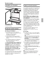
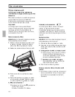
You can move the operating unit from
the middle of the filter drawer to the left
or right side.
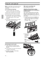
The operating unit can also be fitted at the
front in a handle moulding available as an
optional accessory or in the enclosed
handle moulding (see optional accessories
on back page).
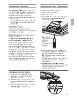
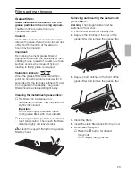
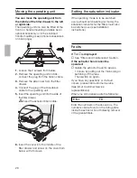
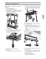
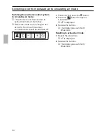
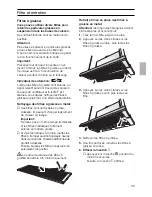
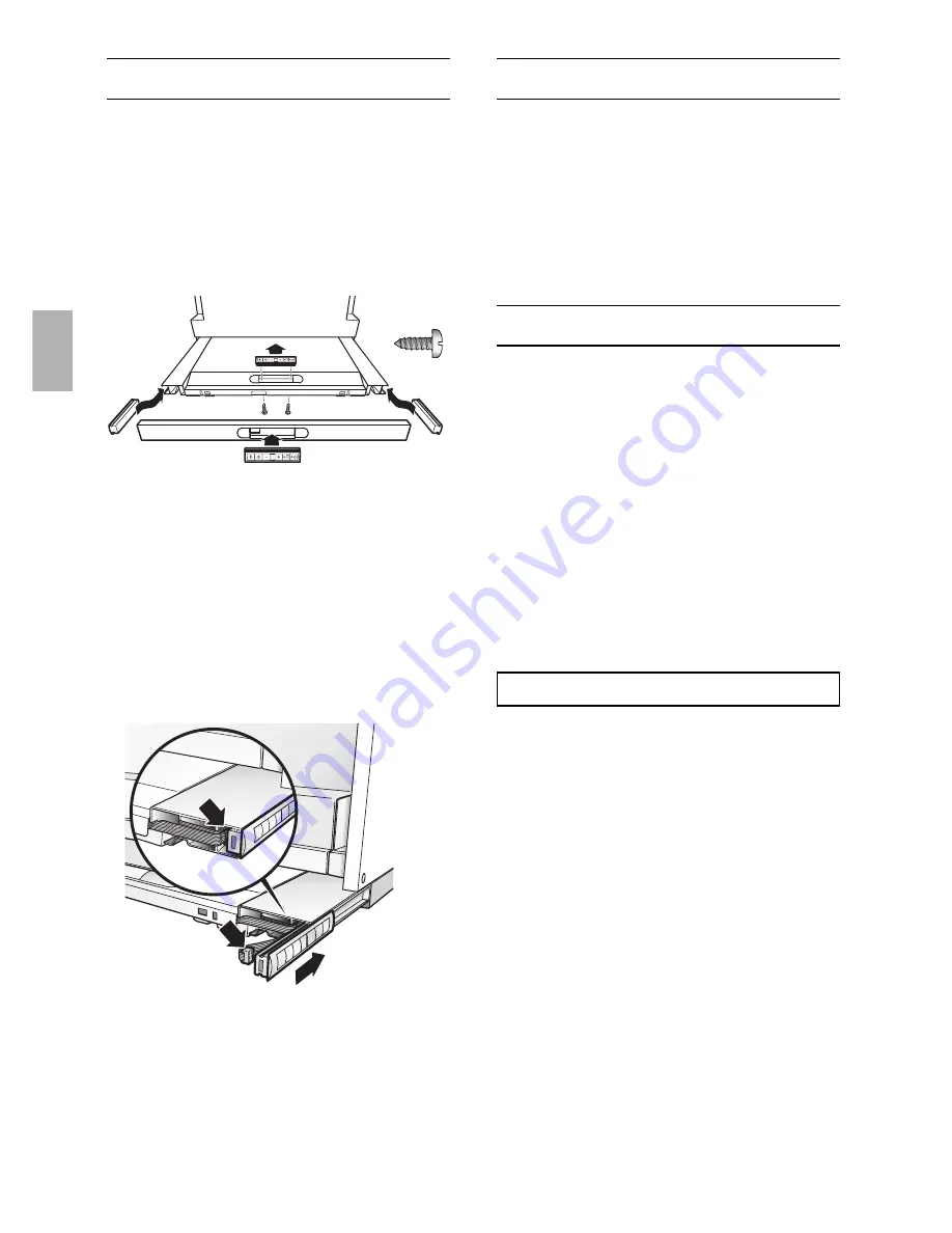
Moving the operating unit
1.
Loosen the 2 screws from below.
2.
Remove the operating unit and dis-
connect the plug from the ribbon cable.
3.
Remove the side cover from the filter
drawer.
4.
Connect the plug of the side ribbon
cable to the operating unit.
5.
Insert the operating unit into the side of
the filter drawer.
Insert the excess ribbon cable.
6.
Insert the cover into the middle of the
filter drawer and screw on the cover from
below with 2 screws.
Setting the saturation indicator
If the operating mode is to be switched
over (exhaust air/circulating air mode), the
saturation indicator for the filters must also
be switched over (see Installation
instructions).
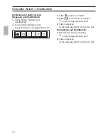
Faults
If
#
or
ã
is displayed:
❑
See "Filters and maintenance" Section.
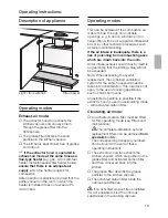
If the extractor hood cannot be
operated:
❑
Isolate the extractor hood for approx.
1 minute by pulling out the mains plug or
switching off the fuse.
Then switch on again..
If you have any questions or if a fault
occurs, please call Customer Service.
(See list of Customer Service
representatives).
When you call, please quote the following:
E-Nr. FD
Enter the numbers in the above box. The
numbers can be found on the rating plate
inside the extractor hood following removal
of the grease filters.
Summary of Contents for DA89B
Page 99: ...99 D 4 Pa 0 04 mbar...
Page 100: ...100 T E A...
Page 101: ...101 L 1 10 2 off on On Off On Off 5 55...
Page 102: ...102 2 L 10 a a 3 3...
Page 103: ...103 1 2 4 5 6 L 3 3 6...
Page 104: ...104 A 1 2 3 4 3 4 5 L 3 6 1 2...
Page 105: ...105 3 12 Volt 20 Watt G4 4 5 1 2...
Page 106: ...106 1 2 2 3 4 5 6 2 1 FD...
Page 107: ...107 650 mm 1 Hs 03 0 kW 08 3 kW 03 9 kW 03 9 kW 11 3 kW 430 mm 1 TRGI 300 mm...
Page 108: ...108 D D 4 Pa 0 04 mbar...
Page 110: ...110 600 mm 293 350 mm 435 mm 293 mm O II 0 5 mm 1 l 2 mm 10 mm O II 2 3 1...
Page 111: ...2 7 8 9 1 2 5 2 6 4 2 111...
Page 112: ...112 2 1 O III l 2 mm 10 mm 16 0 16 5 kg...
Page 113: ...113 1 2 3 4 1 30 m 3 mm LS 5 6 1 2 3 2...
Page 114: ...114 1 L 2 3 3 1 2...


