


Magna Track LS
EN
12
6
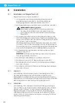
Installation
6.1
Installing Magna Track LS
Install Magna Track LS as follows:
1.
Place all the track profiles in line with each other on the floor, see
Figure 14. Screw the profiles together with the lengthening joints, see
Figure 2.
2.
Fasten the mounting devices in the middle of every other profile, see
Figure 3.
WARNING!
Risk of personal injury.
When mounting Magna Track LS, check that the system will not
snag on protruding parts on the vehicle when exiting or entering
the station.
3.
Lift the whole track and fit it to the ceiling supports, see Figure 4. The
mounting devices is to be fixed in bars, brackets or similar arrangements
according to the examples. The first and the last mounting bracket is to be
braced, see Figure 4, item 1 and 2.
All mounting brackets are to be braced with bracing bars positioned
sideways according to either item 3 or 4 in Figure 4. When mounting the
track, ensure that suitable fixing bolts are used considering the ceiling
construction material, and the traction forces in the suspension points.
4.
Attach the duct connector over the track as close to the middle of the track
as possible, see Figure 8.
NOTE!
The vehicle’s parking position must be on the opposite side of the
track, see Figure 1.
5.
Slide the trolley with balancer, see Figure 6.
6.
Attach the balancer cord to the 90°-bend, see Figure 7.
7.
Install the shock absorber in the front of the guide track, see Figure 8,
item 1.
8.
Install the screw and nut at the rear of the guide track, see Figure 8,
item 2.
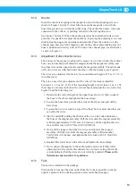
6.1.1
The exhaust pipe
See Figure 9. The pipe is to be straight and lie flush with or protrude slightly
out from the side of the vehicle. Also, note the minimum distance from the
bottom of the coachwork and the back wheel. It is possible that modifications
may be required to the exhaust system of the vehicle to ensure the optimum
position of the exhaust pipe.
6.1.2
Anchor plate
See Figure 9. The anchor plate is to be fitted to the side of the vehicle, 600 mm
(2 ft) from the exhaust pipe. If necessary, this distance can be changed (+100
mm (4 in), –25 mm (–1 in)) by loosening the adjusting screw in the magnetic
unit, see Figure 10, item X. Secure the attachment of the anchor plate to the
vehicle to withstand the release force. (180 N ± 18 N (40 lbs ± 4 lbs) when
automatic release at exit, 550 N (125 lbs) when manual pull off straight out.)


