NED
SUCL2025T3
UME-0017-08
18
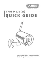
3.3 Connectors / Pin Assignments / Cables
This camera uses the Medium Configuration (8 bit output) of the Camera Link interface
standard. The figure shown below shows the interface for the camera and a typical
implementation for the frame grabber interface in the case of Medium Configuration.
Figure 3-3-1 Camera / Frame Grabber Interface
28
28
Frame Grabber Board
Camera
2
6
-p
in
M
DR
Con
n
e
c
to
r
CL1
CC1(control input)
Cable
SerTC
SerTFG
CK60MHz(8060SA)
Channel Link Bus
LVAL,FVAL
DVAL,SP
PortA~C
CC2
CC3
CC4
X1±
X0±
X2±
X3±
XClk±
100
Ω
100
Ω
100
Ω
100
Ω
100
Ω
100
Ω
100
Ω
100
Ω
100
Ω
100
Ω
100
Ω
SerTFG±
SerTC±
CC1±
CC2±
CC3±
CC4±
2
6
-p
in
M
DR
Con
n
e
c
to
r
X1±
X0±
X2±
X3±
XClk±
SerTFG±
SerTC±
CC1±
CC2±
CC3±
CC4±
LVDS_DRIVER(NS)
DS90CR285MTD
equivalent
LVDS_DRIVER/
RECEIVER(NS)
DS90LV019TM
equivalent
LVDS_RECEIVER(NS)
DS90LV048AT
equivalent
LVDS_RECEIVER(NS)
DS90CR286MTD
recommended
LVDS_DRIVER/
RECEIVER(NS)
DS90LV019TM
recommended
LVDS_DRIVER(NS)
DS90LV047AT
recommended
28
28
2
6
-p
in
M
DR
Con
n
e
c
to
r
CL2
Cable
Channel Link Bus
LVAL,FVAL
DVAL,SP
PortD~F
Y1±
Y0±
Y2±
Y3±
YClk±
100
Ω
100
Ω
100
Ω
100
Ω
100
Ω
100
Ω
100
Ω
100
Ω
100
Ω
100
Ω
100
Ω
terminated
100
Ω
terminated
2
6
-p
in
M
DR
Con
n
e
c
to
r
Y1±
Y0±
Y2±
Y3±
YClk±
LVDS_DRIVER(NS)
DS90CR285MTD
equivalent
LVDS_RECEIVER(NS)
DS90CR286MTD
recommended
CK40MHz(8040SA_6040SA)
CK40MHz(8040SA_6040SA)
CK60MHz(8060SA)