background image

XN120 Battery Box 


                   XN120 Battery Box Guide 

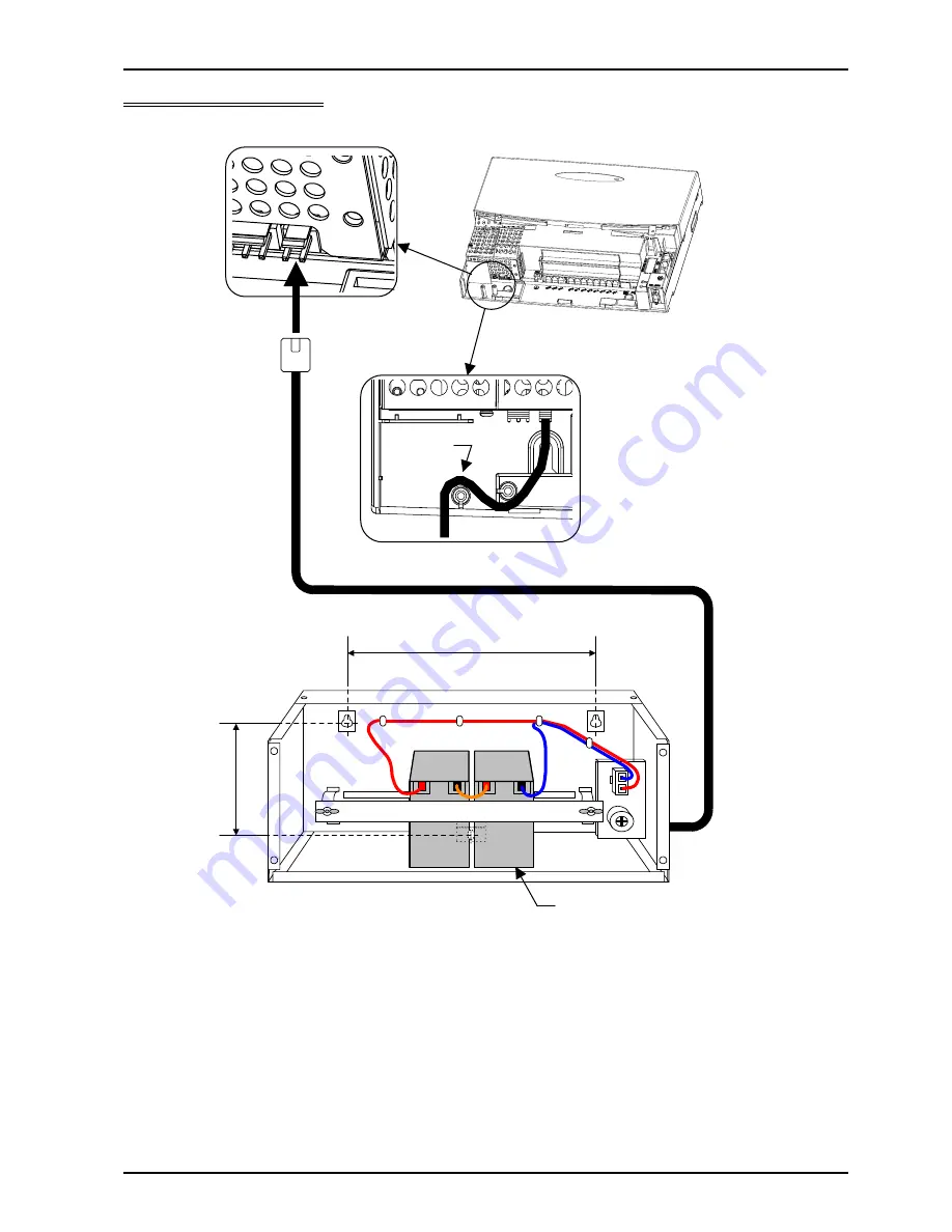
Connection Diagram 


Batteries 

-

-

280 mm 

155 mm 

XN120 Main or Expansion Unit 

Battery
Cable 

XN120 Battery Box 

Battery box connecting cable (2.5 metres) 

Summary of Contents for XN120 Vision

Page 1: ...ation supplied for future reference Regulatory Notice Refer to the Getting Started Guide 991409 5 supplied with the XN120 Main Unit for the Declaration of Conformity related to the product Warning Thi...

Page 2: ...the Battery Box 5 2 Wall Floor Mount the Battery Box 6 3 Install the batteries 7 4 Connect the Battery Box to the XN120 8 5 Connect the Power System Start Up 9 6 Configure the XN120 10 7 Test the Powe...

Page 3: ...uasa 2 6Ah 12V Battery Specification Battery capacity 12V 2 6Ah or equivalent Voltage must be 12V Battery Only the manufacturer and type of battery specified must be used Yuasa NP2 6 12 134x67x64 mm 1...

Page 4: ...XN120 Battery Box 4 XN120 Battery Box Guide Connection Diagram Batteries 280 mm 155 mm XN120 Main or Expansion Unit Battery Cable XN120 Battery Box Battery box connecting cable 2 5 metres...

Page 5: ...of connecting cable attached 3 screws for securing the box to the wall Battery retaining bar with 2 fixing brackets 2 wing nuts for the battery retaining bar 2 Orange cables 1 required when used for...

Page 6: ...unit the connecting cable is 2 5 metres long 2 Loosen the 4 screws on the front of the battery box and remove the front cover 3a Floor Shelf mounting Position the battery box on the floor shelf Secur...

Page 7: ...e of the orange cables connect the ve terminal of one of the batteries to the ve terminal of the OTHER battery CAUTION DO NOT SHORT CIRCUIT the battery terminals 4 Connect the batteries to the socket...

Page 8: ...are installed 2 Remove the sub cover of the XN120 Unit 2 Connect the cable from the battery box to the socket in the XN120 unit The plug on the battery box connecting cable is polarity sensitive ensu...

Page 9: ...on the system check that the NORMAL switch is set to ON This will ensure that the system memory retains your configuration The NORMAL switch is located to the right of the MOH Page connector on the m...

Page 10: ...s become discharged The XN120 unit is considered to be in battery back up mode at this time it is not in power fail mode When the batteries are discharged the XN120 unit will stop working the XN120 is...

Page 11: ...teries are of a sealed valve regulated type gases may be released from the batteries Do not install the battery box in a sealed enclosure Never short circuit the battery terminals There is a risk of e...

Reviews: