background image

856-180423-001-00 

- 1 - 


大切に保管してください。


N8106-010 VMware ESXi

ベースキット


組み立て・取り扱いの手引き


組み立てを行う前に


この度は、本製品をお買い上げいただきまして誠にありがとうございます。 


本製品を取り扱う前に本書の内容をよく読み、指示に従ってください。また、本製品を取り付ける前に、 
取り付ける本体に添付の「ユーザーズガイド」に記載されている注意事項も参照してください。 

また、増設にあたっては、最寄りの保守サービスセンターに依頼することをお勧めします。 


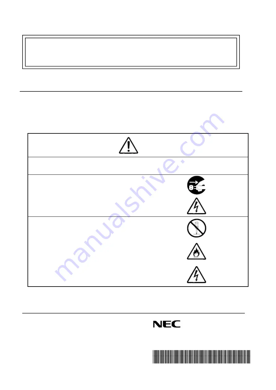
警告


  安全上のご注意を無視する取り扱いを行うと、装置の故障、人体事故、火災・周囲の機器の損傷を


  引き起こす原因となることがあります。


オプションの取り付け、取り外し時は電源プラグをコンセントから


抜き、外部装置と接続しているケーブルを外してください。


故障や感電する恐れがあります。


電源プラグを抜く


感電注意


本書に記載されている場合を除き、絶対に分解したり、修理・改造を

行ったりしないでください。装置が正常に動作しなくなるばかりで


なく、感電や火災の危険があります。


分解禁止


発火注意


感電注意


N8106-010 VMware ESXi

ベースキット


組み立て・取り扱いの手引き 


* 856-180423-001-00 * 

Summary of Contents for VMware ESXi N8106-010

Page 1: ...ユーザーズガイド に記載されている注意事項も参照してください また 増設にあたっては 最寄りの保守サービスセンターに依頼することをお勧めします 警告 安全上のご注意を無視する取り扱いを行うと 装置の故障 人体事故 火災 周囲の機器の損傷を 引き起こす原因となることがあります オプションの取り付け 取り外し時は電源プラグをコンセントから 抜き 外部装置と接続しているケーブルを外してください 故障や感電する恐れがあります 電源プラグを抜く 感電注意 本書に記載されている場合を除き 絶対に分解したり 修理 改造を 行ったりしないでください 装置が正常に動作しなくなるばかりで なく 感電や火災の危険があります 分解禁止 発火注意 感電注意 N8106 010 VMware ESXi ベースキット 組み立て 取り扱いの手引き 856 180423 001 00 ...

Page 2: ...ルダ 1 4 保証書 1 5 VMware ESXi ベースキット 組み立て 取り扱いの手引き 1 本書 取り扱い上の注意事項 本製品を箱から取り出した後は 次の注意事項を必ずお守りください ほこりの多い場所や水などの液体のかかるおそれのある場所に置かないでください 強い磁気を発生させるものの近くに置かないでください USB DOMの端子部分には触れないでください 第三者への譲渡 本製品を第三者へ譲渡 または売却 する場合には 本書を一緒にお渡しください この装置は クラス B 情報技術装置です この装置は 家庭環境で使用 することを目的としていますが この装置がラジオやテレビジョン受信機に 近接して使用されると 受信障害を引き起こすことがあります 取扱説明書に従って正しい取り扱いをして下さい VCCI B ...

Page 3: ...源を OFFにしてください 2 本製品は静電気に弱い電子部品で構成されています 取り付け 取り外しの際は 静電気による製品の故障に十分注意してください 2 VMware ESXi ベースキットの取り付け 1 サーバモジュールの取り外し 1 Express5800 E120f M ユーザーズガイド の 2 章 1 3 取り付け 取り外しの概要 の 手順 1 3 を参照して準備します 2 ロック機構を右に押しながらハンドルを上に持ち上げます ハンドルを持って 水平方向に サーバモジュールを引き出します モジュールエンクロージャからサーバモジュールを抜き 再びモジュールエンクロージャに 挿すときは 30 秒以上経過してから挿し込んでください ...

Page 4: ...856 180423 001 00 4 2 VMware ESXi ベースキットの取り付け Express5800 E120f M ユーザーズガイドの 2 章 1 2 静電気対策 を参照し 静電気対策した上で作業してください VMware ESXi ベースキットの搭載場所 サーバモジュール 左 サーバモジュール 右 ...

Page 5: ...856 180423 001 00 5 1 USB 延長ケーブルを USB DOM に接続し そのままホルダに搭載します 取り外した USB DOM のキャップは紛失しないよう保管してください ...

Page 6: ...856 180423 001 00 6 2 USB DOM セットをサーバモジュール内に差し込みます 上から降ろします 装 置 前 面 USB DOM 搭載位置 ...

Page 7: ...856 180423 001 00 7 3 ホルダを後方へスライドさせつつ ホルダのフックをロックし サーバモジュール底板の スリットにホルダ底面の凸部を引っかけます USB ホルダをサーバモジュールに固定するための各部位は下記位置です フック部分 凸部分 ...

Page 8: ...856 180423 001 00 8 HDD 格納 Bracket の側面にある穴に ホルダのフック部分の凸を差し込んで セットします HDD 格納 Bracket 側面部 ホルダのフックが正常にロックされた状態 ...

Page 9: ...856 180423 001 00 9 ホルダを後方へスライドさせながら サーバモジュールの底板にあるスリットに ホルダ底面の凸部分を差し込みます サーバモジュール底板のスリット位置 拡大 スリットにホルダ凸部が正常に差し込まれた状態 ...

Page 10: ...856 180423 001 00 10 4 USB 延長ケーブルを繋げます VMware ESXi ベースキットのケーブル ルーティング サーバモジュール 左 サーバモジュール 右 マザーボード上のケーブルコネクタ接続箇所 USB DOM 冷却スポンジの下に通します ケーブルタイ ケーブルタイ ケーブルタイ USB DOM 冷却スポンジの下に通します ケーブルタイ ケーブルタイ ケーブルタイ ...

Page 11: ...ブルの下に USB 延長ケーブルを通すようにしてください そうすることで USB 延長ケーブルが飛び出すことを防げます ケーブルの余長部分は マザーボード側で処理してください 5 VMware ESXi ベースキット取り付け作業のため取り外した部品があれば 元に戻します 6 サーバモジュールをエンクロージャの元の位置に挿入します STATUS LED がアンバー点灯しますので消灯するまで待ち 約 40 秒 消灯後サーバモジュールの電源を ON にします ケーブルの余長部分 ...

Page 12: ...項目 出荷時の値 設定値 Boot Boot Mode UEFI Legacy Advanced Processor Configuration X2APIC Enabled Disabled OS インストール後は必ず BIOS SETUP メニューの以下の項目を本製品に設定してください 項目 設定値 Boot HDD Priorities Boot Option 1 SwissbitUSB Flash Module2000 This device is the USB DOM インストールメディアをセットした後に電源を ON にしてください インストーラが自動起動すると Storage Device の選択画面が表示されます local にある約 3 74GB の USB デバイスを選択してインストール作業を進めます 本 USB デバイスへ ESXi をインストールした場合 スクラッチ...

Page 13: ...ary For the server in which the Kit is installed refer to the User s Guide of the server Read Notes on Use carefully before handling the Kit WARNING Indicates the presence of a hazard that may result in death or serious personal injury When you install the option or delete it unplug the power cord and extract the cable that has connected to another one Otherwise an electric shock or fire may be ca...

Page 14: ...e place where dust water or liquid may pour Do not use the server in the place where the strong electromagnetic waves generate Do not touch the terminals or component of the product by a bare hand Transfer to Third Party Make sure to provide this manual and all the accessories along with the product to a third party Regulatory Notices WEEE Directive ...

Page 15: ...upport kit is that used on Express5800 E120f M Composition article This kit including the following parts please check it No Name Quantity Comment 1 USB DOM 4GB 1 2 USB extend cable 1 3 USB DOM holder 1 4 VMware ESXi support Kit User s Guide 1 This book ...

Page 16: ...ou need to remove server module from rack when installing the VMware ESXi support kit 1 Refer to steps 1 to 3 in Express5800 E120f M User s Guide Chapter 2 1 3 Overview of Installation and Removal for preparations 2 Lift the lever while pushing the locking mechanism toward right Hold the handle and pull out the server module horizontally Important If you remove the server module from module enclos...

Page 17: ... kit Important You must avoid static electricity to work with the procedure below For details refer to Express5800 E120f M User s Guide Chapter 2 1 2 Anti static Measures Installation place of VMware ESXi support kit Left server module Right server module ...

Page 18: ...856 180423 001 00 18 1 Connect the USB DOM to a USB extend cable and then install into a USB DOM holder Important Keep so that a lid of removed USB DOM isn t lost ...

Page 19: ...856 180423 001 00 19 2 Push the USB DOM straight into the server module Installation place of USB DOM Server Module Front ...

Page 20: ... to back side At the same time lock holder s hook and insert holder s projection part into a slit in the drawer bottom of server module Note There is each part to fix a USB DOM holder on server module at the following place Projection part Hook ...

Page 21: ...856 180423 001 00 21 Tips Insert the hook s projection part of holder in the hole at the side of HDD bracket The side part of a HDD bracket The state that holder s hook locked normally ...

Page 22: ... the back at the same time insert holder s projection part into a slit in the drawer bottom of server module The place of slit in the drawer bottom of server module Enlarged drawing The state that holder s projection part inserted into a slit normally ...

Page 23: ...te of the VMware ESXi support kit s cable Left server module Right server module The USB extend cable connector on the motherboard USB DOM Pass the cable under the cooling sponge Cable tie Cable tie Cable tie USB DOM Pass the cable under the cooling sponge Cable tie Cable tie Cable tie ...

Page 24: ...f cable on the motherboard 5 Additionally when there is a part removed for installing an internal optional device please return it to the original location 6 Please insert the server module in the original location of the enclosure The STATUS LED lights amber so please wait for about 40 seconds until turn off the lights and turn on the power The excess length of cable ...

Page 25: ... Configuration X2APIC Enabled Disabled Please set the HDD Priorities Boot Option 1 to SwissbitUSB Flash Module2000 USB DOM by BIOS setup menu after OS installation Item To be changed Boot HDD Priorities Boot Option 1 SwissbitUSB Flash Module2000 This device is the USB DOM Set the install media to ODD then DC ON After auto boot the installer Storage Device select menu will appear Select the USB dev...

Page 26: ...856 180423 001 00 26 M e m o N8106 010 VMware ESXi support kit User s Guide 856 180423 001 00 ...

Reviews: