1-8
System Overview
!
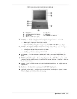
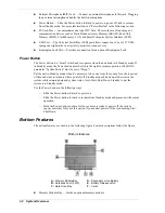
External Microphone (MIC) Jack — Connect an external microphone to this jack. Plugging
in an external microphone disables the built-in microphone.
!
Power Button — Slide the Power button forward to power on, power off, and to resume
from Standby mode. For more information, see “Power Button” in the following section.
!
PC Card Slot — Accommodates one type II PC Card. These cards are often storage or
communication devices such as Static Random Access Memory (SRAM), Read Only
Memory (ROM), Flash Memory, LAN, and Small Computer System Interface (SCSI).
!
USB Port — The Universal Serial Bus (USB) port allows connection of up to 127 USB-
equipped peripheral devices (printers, monitors, scanners, etc.).
!
Kensington Lock Slot — Provides a connection for an optional Kensington Lock.
Power Button
The Power button is a “smart” switch and recognizes when the notebook is in Standby mode. If
in Standby mode, the Power button must be slid to the right to resume operation. (The BIOS
parameter “System Switch” must be set to “Sleep.”)
Put the unit in Standby mode when it’s necessary to be away from the system for a short period
of time and want to return to where you left off. Standby mode shuts down all devices in the
system while retaining data and system status. Go to Start, Shut Down, Standby to put the
system into Standby mode.
Use the Power button in the following ways:
—
Slide the Power button forward to power on.
—
Slide the Power button forward to resume from Standby mode and proceed with normal
operation.
—
Hold the Power button in place for four or more seconds to power off the system
(power override). Only use this option if you cannot power off the system using Start,
Shut Down.
Bottom Features
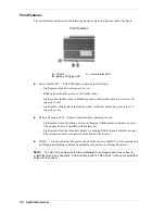
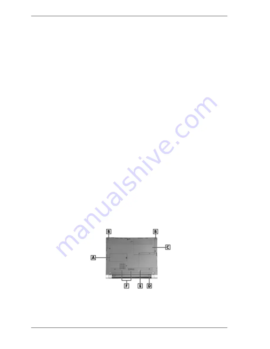
The bottom features are shown in the following figure. Feature descriptions follow the figure.
Bottom features
A
– Memory Module Bay
D
– Secondary Li-Ion Battery
B
– Notebook Feet (2 of 5)
E
– Battery Release Latch
C
– Hard Drive Bay
F
– Vents
!
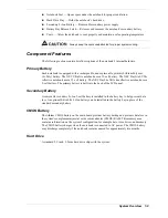
Memory Module Bay — Holds an optional memory module.
Summary of Contents for VERSA ULTRALITE
Page 42: ...3 Disassembly and Reassembly Required Tools and Equipment Disassembly Reassembly...
Page 58: ...5 Illustrated Parts Breakdown Illustrated Parts Breakdown Parts List...
Page 65: ...7 Troubleshooting Problem Checklist Startup Problems Diagnostics...
Page 73: ...8 NEC Computers Information Services Service and Support Functions Technical Support...
Page 76: ...9 Specifications System Components Memory Map Interrupt Controllers...


