background image

Regulatory Statements   1

Regulatory Statements

The following regulatory statements include the Federal Communications Commission
(FCC) Radio Frequency Interference Statement, compliance statements for Canada and
Europe, and battery disposal and replacement information.

FCC Statement for United States Only

Changes or modifications to this unit not expressly approved by

the party responsible for compliance could void the user’s authority to operate the
equipment.

Note 

  This equipment has been tested and found to comply with the limits for a Class B

digital device, pursuant to Part 15 of the FCC Rules. These limits are designed to provide
reasonable protection against harmful interference in a residential installation. This
equipment generates, uses and can radiate radio frequency energy and, if not installed and
used in accordance with the instructions, may cause harmful interference to radio
communications.

However, there is no guarantee that interference will not occur in a particular installation. If
this equipment does cause harmful interference to radio or television reception, which can
be determined by turning the equipment off and on, the user is encouraged to try to correct
the interference by one or more of the following measures.

!


Reorient or relocate the receiving antenna.

!


Increase the separation between the equipment and receiver.

!


Connect the equipment to an outlet on a circuit different from the one to which the
receiver is connected.

!


Consult the dealer or an experienced radio/TV technician for help.

Canadian Department of Communications Compliance Statement

This Class B digital apparatus meets all requirements of the Canadian
Interference-Causing Equipment Regulations (pursuant to ICES-003
Issue 2, Revision 1).

Avis de conformité aux normes du ministere des communications du Canada

Cet equipment numérique de la Classe B respecte toutes les exigences du Reglement sur le
matérial brouillage du Canada (en conformité avec ICES-003 Emission 2, Révision 1).

European Community Directive Conformance Statement

This product is in conformity with the protection requirements of EC Council Directive
89/336/EEC on the approximation of laws of the Member States relating to electro-
magnetic compatibility. This product satisfied the Class B limits of EN55022.

Summary of Contents for VERSA ULTRALITE

Page 1: ...U ULTRA LTRA LTRA LTRAL L L LITE ITE ITE ITE D D D DAY AY AY AYL L L LITE ITE ITE ITE S E R V I C E A N D R E F E R E N C E S E R V I C E A N D R E F E R E N C E S E R V I C E A N D R E F E R E N C E...

Page 2: ...tation by customers of each product may vary the suitability of specific product configurations and applications must be determined by the customer and is not warranted by NEC To allow for design and...

Page 3: ...apter 2 2 Powering on the System 2 3 Batteries 2 4 Extending Battery Life 2 4 Determining Battery Status 2 4 Low Battery Status 2 5 Charging the Battery 2 5 Secondary Battery Handling 2 5 Precautions...

Page 4: ...3 12 LCD Panel 3 13 Reassembly 3 13 4 System Boards Mini PCI Board 4 2 Power Switch Board 4 2 USB Connector Board 4 2 Main Board 4 3 Communications Board 4 3 5 Illustrated Parts Breakdown Illustrated...

Page 5: ...Contents v 9 Specifications System Components 9 2 Memory Map 9 7 Interrupt Controllers 9 8 Glossary Index...

Page 6: ...tup and how to operate the notebook Chapter 3 Disassembly and Reassembly provides detailed instructions on how to disassemble the notebook Chapter 4 System Board Layout shows the system boards and the...

Page 7: ...ing system DRAM dynamic RAM DVD digital video disk ECC error checking and correction ECP enhanced capabilities port EDO extended data output EGA Enhanced Graphics Adapter EPP enhanced parallel port EP...

Page 8: ...OM QFP quad flat pack RAM random access memory RAMDAC RAM digital to analog converter RAS row address strobe RGB red green blue RGBI red green blue intensity ROM read only memory rpm revolutions per m...

Page 9: ...1 System Overview About the NEC Versa Notebook Front Features Back Features Left Side Features Right Side Features Bottom Features Component Features Chipset Features...

Page 10: ...ooks are similar differing mainly in the type of LCD panel and in the type of primary and secondary batteries Additionally the NEC Versa DayLite notebook with the transflective LCD panel has an on off...

Page 11: ...ly Provides backlighting to the reflective LCD panel Switch up position is on down position is off Microphone Allows recording of monophonic sound directly into the notebook hard drive NEC VersaGlide...

Page 12: ...ng figure Feature descriptions are provided after the figure Keyboard A Function Keys D Cursor Control Keys B Numeric Keys E Control Keys C Windows keys Function keys Twelve function keys F1 through F...

Page 13: ...again the keys revert to their normal functions as typewriter keys Cursor Control keys Cursor control keys let you position the cursor on the screen where you want On the screen the cursor is a blinki...

Page 14: ...y or less Battery Charging LED lights to indicate battery charging activity Lights amber when the primary battery is charging Blinks amber to indicate an error The primary battery is installed in the...

Page 15: ...he notebook The LCD display and external monitor can be run simultaneously or run alone RJ 11 Jack Connects the internal modem to an analog telephone line USB Port The Universal Serial Bus USB port al...

Page 16: ...mode the Power button must be slid to the right to resume operation The BIOS parameter System Switch must be set to Sleep Put the unit in Standby mode when it s necessary to be away from the system f...

Page 17: ...ctive notebook uses a 12 cell battery The NEC DayLite XGA transflective notebook uses a 9 cell battery The primary battery is built into the back of the LCD panel Secondary Battery A removable seconda...

Page 18: ...nufacturer Description TransMeta TM5600 Crusoe TransMeta 600 MHz CPU 82440MX Intel System Controller FDC37N869 Standard Microsystems Super I O SM721 Silicon Motion Video EV1938 Creative Technology Aud...

Page 19: ...2 System Configuration and Setup Power Sources BIOS Setup Updating the BIOS Transmeta LongRun Utility NEC Customize Utility Application and Driver CD Product Recovery CD...

Page 20: ...er charges the battery when it is connected whether the notebook is powered on or off AC adapter A AC Adapter C Power Cable B Adapter Cable Do not disassemble the AC adapter The AC adapter has no repl...

Page 21: ...tem Powering on the System Power on the system as follows 1 Locate the latch on the front of the notebook slide it to the right and raise the LCD panel 2 Locate the Power button and slide it forward t...

Page 22: ...ment You can use the LongRun utility to force the processor to run at a slower speed extending battery run time Note that add in PC Cards increase battery usage reducing battery run time Keep the note...

Page 23: ...secondary batteries by connecting the notebook to an AC power source It takes approximately 8 hours to fully charge the battery while the notebook is on and 4 5 hours while off To monitor the charging...

Page 24: ...casing is discolored overheats or emits a foul odor Keep the battery dry and away from water Keep metal objects away from battery connectors Metal objects in contact with the connectors can cause a sh...

Page 25: ...Bay Release Latch 5 Install the new secondary or optional Extra Life battery as follows Locate the alignment grooves on the edge of the battery and inside the battery bay see the following figure Ali...

Page 26: ...matically If you want to fix the error carefully read the error message that appears above the prompt taking notes if you want and press F2 You will see this message if the CMOS battery becomes fully...

Page 27: ...ed submenu then press Enter An Item Specific Help window on the right side of each menu displays the help text for the currently selected Setup option It updates as the cursor moves to each new field...

Page 28: ...ve type Bring up the Diskette A submenu by pressing Enter Internal HDD Displays the HDD capacity Example xxxxx MB Bring up the Internal HDD submenu by pressing Enter The submenus include Type and LBA...

Page 29: ...ormat the drive If a drive is run in a mode other than the mode in which it was partitioned and formatted unpredictable results may occur including data loss When set to None informs the system to ign...

Page 30: ...ata to and from the drive Autotype the drive to select the optimum transfer mode When Type is set to Auto the value in the field is auto detected and the field is read only Advanced Menu Choose the Ad...

Page 31: ...I O Device Configuration submenu to configure the IR serial port On Board Device Configuration Press Enter to view submenu USB Device Enable Disable Security Menu Choose the Security menu by selecting...

Page 32: ...enu Settings Menu Item Settings default is bold USB Drive Hard Drive The Boot Menu displays the bootable devices in the current boot order Use the up or down arrows to select a device Press Enter to e...

Page 33: ...ble the BIOS Flash Setting Obtaining the BIOS Update Contact NEC Computers Support Services to obtain the BIOS Update Diskette Or you can download the BIOS update from the NEC Computers web site see S...

Page 34: ...default setting is ON Off is for BIOS Flash Switch 6 Logo select default setting is OFF Use these steps to access the DIP switch in the memory bay and to set a switch 1 Power off the system and disco...

Page 35: ...ected Document all customized BIOS settings 2 Power on the notebook with the BIOS Update diskette in the drive The computer boots and automatically loads the utility A message similar to the following...

Page 36: ...tion If the system is in an idle state or doing processing that doesn t require faster clock speeds it automatically lowers to 300MHz If the system is completing more demanding tasks it adjusts up to...

Page 37: ...ed NEC wallpaper to set the NEC logo as the background image Follow these steps to use the NEC Customize utility 1 Double click the NEC Customize icon on the Windows desktop 2 From the display window...

Page 38: ...tebook to its initial installation state as a last resort Check the problem checklist in Section 7 for information about solving problems before using the CD The Product Recovery utility provides opti...

Page 39: ...ly use the Full Disk Drive restore option if the preinstalled software is unusable Use these steps to perform a Full Disk Drive restore 1 Check the Product Recovery CD title and make sure that it is t...

Page 40: ...r the NEC Versa notebook and operating system 2 Power off the system before connecting the external CD ROM drive to the notebook 3 Put the CD into the CD ROM drive tray close the drive door and reboot...

Page 41: ...eboot or press Alt R to reboot the notebook A series of hardware detection screens display the notebook reboots and the Windows Setup screen appears Follow the on screen instructions to set up Windows...

Page 42: ...3 Disassembly and Reassembly Required Tools and Equipment Disassembly Reassembly...

Page 43: ...unit are shown in Chapter 5 For complete disassembly of the system follow the disassembly order in the following table For disassembly of a specific part go the section containing the part removal pr...

Page 44: ...ny unpainted metal surface on the system to avoid ESD damage Hold a board only by its edges If removing a board place it component side up on a grounded static free surface or in a static free wrapper...

Page 45: ...ose the LCD panel turn over the notebook and locate the memory module bay 3 Remove the screw and bay cover Removing the memory module bay cover A Screw B Memory Module Bay Cover 4 Press the locking ta...

Page 46: ...ss the hard drive from inside the notebook See Top Cover Assembly later in this section for removal procedures 3 Remove the two screws securing the cover Slide the cover out of the notebook Removing t...

Page 47: ...yboard above and between the F8 and F9 keys Removing the keyboard A Keyboard Slot 5 Insert the blade of a small flat blade screwdriver into the slot and pull up on the keyboard enough to gain access t...

Page 48: ...e LCD panel unplug the power cable and disconnect any peripheral devices 2 Remove the secondary battery hard drive cover and keyboard The two screws securing the hard drive cover and the three screws...

Page 49: ...astened to the underside of the top cover Release the cable locks on connectors P9 and P10 on the main board and unplug the two VersaGlide Touchpad cables from the connectors Remove and save the tape...

Page 50: ...e secondary battery hard drive cover keyboard and top cover assembly Note Be sure that the BIOS settings are recorded before removing the CMOS battery Any customized BIOS settings are lost when the CM...

Page 51: ...or P34 G Mini PCI Board B CMOS Battery H CMOS Battery Connector P36 C Main Board Cable Connector P41 I PCI Board Connector P32 under board D USB Connector Board J Power Switch Board E Mini PCI Board C...

Page 52: ...ug the switch board cable from connector P16 on the main board 6 Remove the screws A B C on the figure fastening the main board to the base Removing the main board A Long Screws 2 E Switch Board Conne...

Page 53: ...r P32 Communication Board Remove the communication board as follows 1 Save any open files exit Windows turn off notebook power close the LCD panel unplug the power cable and disconnect any peripheral...

Page 54: ...nd cable locations 5 On each side remove the screw securing the LCD panel hinge bracket to the base the following figure shows the left side hinge bracket and screw the right side is similar 6 Remove...

Page 55: ...4 System Boards Mini PCI Board Power Switch Board USB Connector Board Main Board Communications Board...

Page 56: ...over assembly The board is mounted on the right side of the notebook between the hard drive bay and the side of the base The following figure shows the board and its connectors and ports Power switch...

Page 57: ...nector P2 J Cable Connector P14 not used D USB Port P4 K Keyboard Cable Connector P8 E PC Card Bay L Cable Connector P19 not used F Power Switch Board Cable Connector P16 M Monitor Connector Port P15...

Page 58: ...5 Illustrated Parts Breakdown Illustrated Parts Breakdown Parts List...

Page 59: ...traLite DayLite notebook computers illustrated parts breakdown IPB is shown in the following figure See the table Field Replaceable Parts List later in this chapter for a list of field replaceable uni...

Page 60: ...sembly 9 Speaker Assembly 10 128 MB Memory Module 11 Communications Board G7EWKBA 1 3 12a 12b Top Cover VersaGlide Touchpad 13 Keyboard 14 LCD Panel shown for reference purposes only 15 Secondary Batt...

Page 61: ...klight LCD Panel DayLite Reflective LCD Panel DayLite Transflective LCD Panel UltraLite Backlight LCD Cable DayLite Reflective LCD Cable DayLite Transflective LCD Cable UltraLite Backlight Inverter Da...

Page 62: ...6 Preventive Maintenance Cleaning the Exterior Cleaning the Interior Protecting the Hard Disk Drive Maintaining the Secondary Battery...

Page 63: ...f necessary use a small soft bristle brush to clean between the keys 5 Periodically use a head cleaning diskette in the USB diskette drive to prolong the life of the drive and to help maintain data in...

Page 64: ...the battery for evidence of corrosion and oxide build up Observe the following precautions when handling the secondary battery Observe the safety precautions outlined under Secondary Battery Handling...

Page 65: ...7 Troubleshooting Problem Checklist Startup Problems Diagnostics...

Page 66: ...into a working electrical outlet Test the outlet by plugging in a lamp or other electrical device Check that all cables are securely plugged in Check that the display setting is configured correctly...

Page 67: ...rtup Problems The notebook displays an invalid configuration error message at power on and when there are the following conditions current configuration information doesn t match configuration informa...

Page 68: ...ry on the main board is different than the amount in CMOS RAM Run Setup to reset the value CMOS Time and Date Not Set Run Setup to set the time and date Diskette Boot Failure The boot diskette is corr...

Page 69: ...nd try rebooting If you still get a beep code go to the section If You Need Assistance at the end of this chapter Beep Codes are listed in the following table Beep Codes Number of Beeps Error Descript...

Page 70: ...battery is the correct type charged properly and is inserted correctly Power LED is on but no display and notebook does not turn on Check if the memory module is inserted properly Check that the CPU...

Page 71: ...all internal devices Replace the main board USB diskette drive does not work Check if the diskette drive option is set properly in BIOS Setup Check if the diskette USB cable is connected properly Chec...

Page 72: ...r is properly installed Check if the VersaGlide Touchpad cable is firmly connected to P18 on the main board Replace the front panel and VersaGlide Touchpad assembly Replace the main board USB port doe...

Page 73: ...8 NEC Computers Information Services Service and Support Functions Technical Support...

Page 74: ...an use these services to obtain information about the system at any time day or night seven days a week NEC Computers Web Site If you have access to the Internet via a network or a modem connection yo...

Page 75: ...a response to your questions within one business day NEC Computers Technical Support Services NEC Computers also offers direct technical support through its Technical Support Center NEC Computers tec...

Page 76: ...9 Specifications System Components Memory Map Interrupt Controllers...

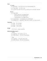
Page 77: ...m memory approximately 16 MB of total system memory shared with video Cache Memory L1 64 KB code and 64 KB data 8 16 way set associate write back data L2 512 KB built in 4 way operates at full core sp...

Page 78: ...ive 10 4 inch high resolution active matrix transmissive reflective XGA 1024 x 768 resolution TFT display Colors 32 bit Graphics ATI RAGE MOBILITY M graphics accelerator with 4 MB VRAM and 2X AGP grap...

Page 79: ...PC Card Slots One 32 bit card slot for a Type II card 5 V or 3 3 V interface 32 bit CardBus support External 24X Maximum 10X Minimum Variable Speed USB CD ROM Drive Type 5 inch CD ROM Pack Average Dat...

Page 80: ...ithium Polymer UltraLite Reflective 12 cell Lithium Polymer Secondary Battery 3 cell Lithium Ion 10 9 volts 2000 mAh Recharging Time Approximately 8 hours when the system is on 4 5 hours when off Dime...

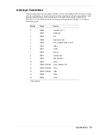
Page 81: ...FFE 0000H FFFF FFFFH 128K Upper ROM System and Video BIOS FFFC 0000H FFFD FFFFH 128K Lower ROM Power Management BIOS FFFA 0000H FFFB FFFFH FFF8 0000H FFF9 FFFFH 128K 128K New Extended Area FFF0 0000H...

Page 82: ...h a cascade connection of 8259INTC x 2 The table shows default interrupt level assignments 0 through 15 in order of decreasing priority Priority Name Device 0 IRQ00 Internal Timer 1 1 IRQ01 Keyboard 2...

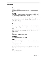
Page 83: ...ps B base RAM Area of system memory between 0 and 640 kilobytes available to the user for operating system and application programs BIOS Basic Input Output System A collection of primitive computer ro...

Page 84: ...en image using tiny dots called pixels See also LCD cursor A movable image on the display screen that indicates where the next entered data appears D diskette A thin flexible platter coated with a mag...

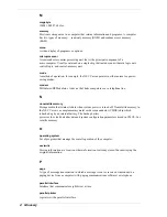
Page 85: ...Drive Electronics A hard disk drive type that has controller electronics built into the drive and delivers high throughput interface A connection that enables two devices to communicate interrupt A s...

Page 86: ...ine N nonvolatile memory Storage media that retains its data when system power is turned off Nonvolatile memory in the NEC Versa is a complementary metal oxide semiconductor CMOS chip which is backed...

Page 87: ...d into the port to attach the device to the computer processor In a computer a functional unit that interprets and executes instructions prompt A special symbol indicating the beginning of an input li...

Page 88: ...lution of 1024x 768 with up to 256 colors displayed simultaneously system board The main printed circuit board inside the system unit into which other boards and major chip components such as the syst...

Page 89: ...mputer without turning off the power through keyboard input pressing Ctrl Alt and Del keys simultaneously or the reset button The system returns to an initial or arbitrarily selected condition write T...

Page 90: ...onnector board 4 2 C Cache memory 9 2 Caps lock 1 4 Charging battery 2 5 Chipset features 1 10 Cleaning notebook exterior 6 2 notebook interior 6 2 CMOS battery 1 9 removal 3 9 Communication board rem...

Page 91: ...13 Microphone 1 3 Mini PCI board layout 4 2 removal 3 10 Monitor port 1 7 N NEC VersaGlide Touchpad 1 3 NEC Computers email support 8 3 Technical support services 8 3 web site 8 2 NEC Customize Utili...

Page 92: ...attery 9 6 Mini PCI LAN modem combo 9 5 PC card slots 9 5 power 9 5 read only memory 9 2 secondary battery 9 6 speaker 9 3 system processor 9 2 Startup problems 7 3 Switch DIP 2 16 System dimensions 9...

Page 93: ...mful interference to radio or television reception which can be determined by turning the equipment off and on the user is encouraged to try to correct the interference by one or more of the following...

Page 94: ...y a replacement incorrect de la batterie Remplacer uniquement avec une batterie du m me type ou d un type recommand par le constructeur Mettre au r but les batteries usag es conform ment aux instruct...

Page 95: ...NEC Computers Inc 15 Business Park Way Sacramento CA 95828 819 200725 000 8 2001 819 200725 000...

Reviews: