Troubleshooting and Repairs 3-11
Frame PCB Main
1.
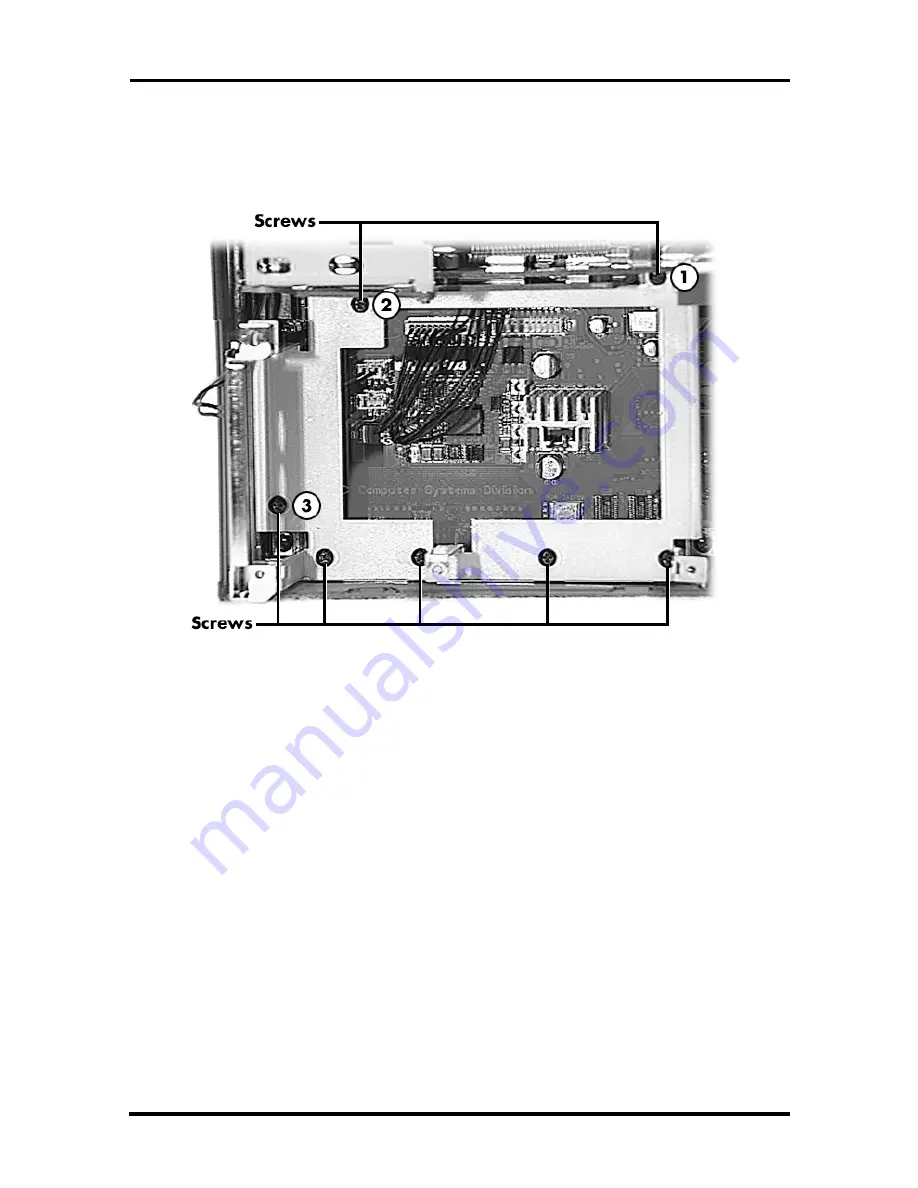
Locate and remove seven screws shown in the following figure:
Figure 3-8 Frame PCB Main
2.
Lift the frame from the sub assembly.
Reassembly
The recommended sequence for inserting and tightening screws is shown in the prior Fig-
ure 3-8 by circled numbers. Follow the sequence indicated by the circled numbers. When
the quantity of screws exceeds the circled numbers, any order maybe used to tighten the
remaining screws.


