background image

Disassembly and Reassembly   3-21

Mini-PCI Option

Use the following steps to remove the Mini-PCI option from the system.

1. 

Remove the keyboard and front cover from the system.

2. 

Remove the screw from the securing bracket. Lift the securing bracket and remove from the
slit in the main board.

3. 

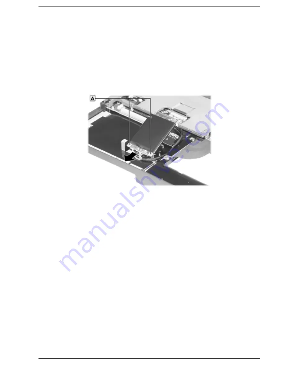
Partially lift the Mini-PCI option up and away from the main board and disconnect it from
connector P9.

Lifting the Mini-PCI option

A – Securing Tab

4. 

Disconnect the cables from connectors P10 and P11 of the main board.

5. 

Pull the Mini-PCI option towards the front of the system to release it from the securing tabs.

CMOS Battery

Use the following procedure to remove the CMOS battery from the system.

1. 

Remove the keyboard, front cover, PC card assembly, and Mini-PCI option (if present)
from the system.

2. 

Disconnect the CMOS battery from connector P19 of the main board.

Summary of Contents for Versa LXi

Page 1: ...NEC Versa Notebook Computer NEC VERSA LXI S E R V I C E A N D R E F E R E N C E M A N U A L...

Page 2: ...ement accompanying each product However actual performance of each such product is dependent upon factors such as system configuration customer data and operator control Since implementation by custom...

Page 3: ...1 13 2 System Configuration and Setup Power Sources for Your NEC Versa 2 2 Using the AC Adapter 2 2 Connecting the AC Adapter 2 2 Powering the System On and Off 2 3 Using the Battery 2 3 Determining...

Page 4: ...ize Utility 2 27 HDPREPEZ Utility 2 27 Using HDPREPEZ in Windows 98 or 95 2 27 Using HDPREPEZ with Windows NT 2 27 Application and Driver CD 2 28 Launching the A D CD with Windows 98 95 2 28 Launching...

Page 5: ...tebook Interior 6 2 Protecting the Diskette Drive and Hard Disk Drive 6 2 Handling the Battery Pack 6 3 Maintaining the LCD Quality 6 3 7 Troubleshooting Quick Troubleshooting 7 2 Helpful Questions 7...

Page 6: ...ebook Chapter 3 Disassembly and Reassembly provides detailed instructions on how to disassembly the notebook Chapter 4 System Board Layout shows the system boards and the board connectors Chapter 5 Il...

Page 7: ...DMA direct memory access DMAC DMA controller DOS disk operating system DRAM dynamic RAM DVD digital video disk ECC error checking and correction ECP enhanced capabilities port EDO extended data outpu...

Page 8: ...PPI programmable peripheral interface PROM programmable ROM QFP quad flat pack RAM random access memory RAMDAC RAM digital to analog converter RAS row address strobe RGB red green blue RGBI red green...

Page 9: ...System Overview Getting to Know the NEC Versa The Front of the System The Back of the System The Left Side of the System The Right Side of the System The Bottom of the System Internal Components Chips...

Page 10: ...14 1 inch or 15 0 inch TFT XGA LCD panel provides high resolution display for sharp effective visuals In addition your system provides a high performance hard disk drive a diskette drive or SuperDisk...

Page 11: ...ore details about using the system s function keys see the section Keyboard later in this chapter Base Unit The base unit of your NEC Versa offers the following features which are described after the...

Page 12: ...or a device in the VersaBay III Diskette Drive lights when the NEC Versa accesses the floppy diskette drive Caps Lock lights when Caps Lock is in effect Scroll Lock lights when Scroll Lock is in effe...

Page 13: ...Windows Keys B Numeric Keys E Control Key C Cursor Control Keys F Control Keys Function keys Twelve function keys F1 through F12 are available on the NEC Versa keyboard These keys work together with...

Page 14: ...ur working environment to a reserved area on the hard drive An additional preprogrammed function key Fn Left Ctrl simulates pressing the right control key for support of IBM 327x connections Numeric k...

Page 15: ...y III A 24X CD ROM drive a SuperDisk drive a 6X DVD ROM drive or a CD read write drive comes installed in the NEC VersaBay III on the front of your system The VersaBay III lets you add options includi...

Page 16: ...yle keyboard to the system With an optional Y cable adapter you can connect both a mouse and a keyboard at the same time Serial Port Connects an external modem or other serial device Parallel Port Con...

Page 17: ...e The TV Out ports do not support the SECAM signal used in some countries Fan Allows your system to cool properly and maintain a safe operating temperature Always keep the fan vents unobstructed to al...

Page 18: ...e stereo as an input source Use a cable to connect to the Line Out port on the other audio system to record or play in stereo External Microphone MIC Connects an external microphone for monophonic rec...

Page 19: ...dules Battery Bay Release Latch Releases and removes the system s main battery NEC VersaBay III Release Lock Unlocks the VersaBay III for device removal NEC VersaBay III A 24X CD ROM drive a SuperDisk...

Page 20: ...y provides the main power source in your NEC Versa LXi computer See Chapter 9 for a list of battery specifications In addition to this battery the CMOS battery and bridge battery also provide system p...

Page 21: ...500 MHz with AGP 600 MHz with AGP and SpeedStep 650 MHz with AGP and SpeedStep Intel 450 MHz CPU 500 MHz CPU 600 MHz CPU 650 MHz CPU Mobil Triton II and 82371MB PIIX4M Intel System Controller PC97338...

Page 22: ...2 System Configuration and Setup Power Sources for Your NEC Versa BIOS Setup Updating the BIOS NEC Utilities Application and Driver CD...

Page 23: ...ting current AC power or to recharge the battery pack Use the AC adapter whenever a wall outlet is nearby Keep the adapter connected whenever possible The AC adapter charges the battery when it is con...

Page 24: ...e the Power button on the right hand side above the keyboard and press it To power off the system press the Power button In Windows the computer automatically shuts down when Shut Down is selected fro...

Page 25: ...r over the power icon on the taskbar to display the remaining battery power for the system s main battery Right click the power icon on the taskbar to open the power meter or to adjust power propertie...

Page 26: ...place it with a fully charged battery Leave the battery pack in the system and connect your NEC Versa to the AC adapter and a wall outlet If you connect the system to AC power and keep the system with...

Page 27: ...e battery out of the reach of children Replacing the Battery The following symptoms indicate that battery life is nearing an end Replace batteries that display these symptoms Shorter work times Discol...

Page 28: ...the battery release latch toward the back of the system and hold firmly Locating the battery bay release latch A Battery Release Latch 4 Continue to hold the battery release latch as you slide the bat...

Page 29: ...cate the alignment groove on the edge of the battery Locate the alignment groove inside the battery bay Align the grooves on the battery with the grooves in the bay Slide the battery into the bay unti...

Page 30: ...act with the terminals can cause a short circuit and damage If the battery leaks If the battery leaks onto skin or clothing wash the area immediately with clean water Battery fluid can cause a skin ra...

Page 31: ...comes low Connect your NEC Versa system to AC power for a full 24 hours before using it on battery power for the first time Doing so insures that the bridge battery is fully charged and that no data i...

Page 32: ...ST to view the BIOS revision number and other POST messages press and hold the Insert key while using the Power button to power on the system The message Ins pressed Press F1 to run setup appears Pres...

Page 33: ...ot available for the current selection Using Keys The following table lists the BIOS Setup keys and their functions BIOS Setup Key Functions Key Function Moves the cursor between the displayed paramet...

Page 34: ...Save Settings and Exit Exit without Saving Resetting System Parameters To reset all parameters to the default settings select Auto Configuration with Defaults from the BIOS Setup Main Menu Use the ar...

Page 35: ...ow keys to move from field to field Use the PgUp or PgDn key to change the numbers within each field Diskette Drives Designates the drive type for your diskette drives Internal Drives Assigns devices...

Page 36: ...D Password Disabled Enabled DS Internal HDD Password 1 Disabled Enabled DS VersaBay HDD Password 1 Disabled Enabled 1 These setup items are only visible when system is docked Assign Supervisor Passwor...

Page 37: ...hard disk drive installed in the NEC VersaBay III Hard disk drive HDD password protection restricts access to the drive if the drive is removed from your NEC Versa and installed in another system You...

Page 38: ...be removed They can be changed If the master password is forgotten and the drive is installed in another system you cannot access the data on the hard drive If the hard drive is installed in another...

Page 39: ...etting Alternate Setting s System Switch Power Button Sleep Button Power Management under AC Off On Power Savings Level Longest Life High Perform Custom Off CPU Speed Control 1 100 12 5 25 50 Hard Dis...

Page 40: ...l Sets CPU performance at one of four levels Hard Disk Timeout Sets the time delay before your hard disk powers down Video Timeout Sets the time delay before your video powers off Peripheral Timeout E...

Page 41: ...h Boot Device 2 1 st Fnd IDE Disabled Floppy SuperDsk CD DVD Try Other Boot Devices Yes No 1 st IDE Hard Drive Internal VersaBay DS Internal DS VersaBay 2 nd IDE Hard Drive VersaBay VersaBay DS Intern...

Page 42: ...Mode Bi Dir Uni Directional ECP EPP IR Serial Port Disabled Auto PnP OS Setup 1 COM2 IRQ3 COM3 IRQ4 COM4 IRQ3 1 Appears only when configured by the Windows 98 or Windows 95 device manager Note If you...

Page 43: ...ransmitted onto your system s microprocessor or central processing unit CPU As indicated in this chapter you use the BIOS Setup utility to configure your system s software and hardware features Use th...

Page 44: ...to make it BIOS flash ready The system prompts you when the process is complete 5 Scan the BIOS Update Diskette for computer viruses The diskette is ready for use 6 Follow the instructions later in t...

Page 45: ...yboard cable entirely from the system 5 Gently rest the keyboard on top of the base unit to view and access the dip switch block Be careful not to twist or disconnect the keyboard cable 6 Locate the d...

Page 46: ...e diskette in the file bay drive The computer boots and automatically loads the utility A message similar to the following appears The NEC BIOS Update Utility should not be used to modify the BIOS in...

Page 47: ...Customize utility HDPREPEZ utility NEC Customize Utility In Windows 98 systems Windows 95 systems and Windows NT systems the NEC Customize utility gives you the option to install or launch NEC custom...

Page 48: ...e NECUTILS HDPREP directory Using HDPREPEZ in Windows 98 or 95 In Windows 98 or 95 run the HDPREPEZ Utility if you increase the memory capacity in your NEC Versa beyond the factory installed base memo...

Page 49: ...Double click the NEC Customize icon if necessary 3 Highlight Launch Application and Driver CD 4 Click launch The Application and Driver CD dialog box appears Launching the A D CD with Windows NT Follo...

Page 50: ...sired software 1 Click the selection tab of your choice 2 Click the desired application driver or utility 3 Click the Install button to install your selection Follow the on screen instructions to inst...

Page 51: ...3 Disassembly and Reassembly Required Tools and Equipment Upgrade Information Disassembly Reassembly...

Page 52: ...thing by touching a nearby metal surface Upgrade Information The NEC Versa LXi supports the following upgrades Hard Disk Drive System Memory The following sections provide instructions on upgrading th...

Page 53: ...the battery release latch toward the back of the system and hold firmly Locating the battery release latch A Battery Release Latch 4 Continue to hold the battery release latch as you slide the battery...

Page 54: ...raised If you encounter any resistance when lifting the lever carefully loosen both sides of the lever before lifting Hard disk drive in the bay A Screw C Hard Disk Drive B Hard Disk Drive Lever With...

Page 55: ...y handle the drive by its sides Lifting the drive out of the bay 6 Replace the new drive as follows Holding the drive by its sides pull up the hard drive lever To avoid damaging the drive do not hold...

Page 56: ...drive toward the connectors and push firmly to secure the connection Do not apply pressure to the drive surface as you push Connecting the drive A Drive Connectors Press down on both sides of the dri...

Page 57: ...ing the battery System Memory Follow these steps to install and if necessary remove a memory module Only install NEC supplied approved memory module options to ensure proper functionality of your NEC...

Page 58: ...screw and bay cover 4 Locate the SO DIMM expansion port and proceed as follows Hold the SO DIMM at a 45 degree angle and align the SO DIMM contacts with the socket in the system Push the connector int...

Page 59: ...assembly illustration to facilitate removal The illustrated parts breakdown and parts lists for the system unit are shown in Chapter 5 For complete disassembly of the system follow the disassembly ins...

Page 60: ...old and new batteries can deteriorate battery and equipment performance 1 Power off the system 2 Close the LCD and turn the system over 3 Slide the battery release latch toward the back of the system...

Page 61: ...l and turn the system over 2 Locate the NEC VersaBay III release lock and release latch on the bottom of the unit NEC VersaBay III release lock and latch A NEC VersaBay III Release Lock B NEC VersaBay...

Page 62: ...Disassembly and Reassembly 5 Pull the device out of the system Note If you release the latch before completely removing the device the device casing catches on the inside of the latch Releasing the de...

Page 63: ...the LCD panel and turn over the system Locate the memory module bay Locating the memory module bay A Screw B Memory Module Bay Cover 2 Remove the screw and bay cover 3 Remove the SO DIMM as follows P...

Page 64: ...notch of the hard drive lever and pull up the lever Be sure that both sides of the lever are raised If you encounter any resistance when lifting the lever carefully loosen both sides of the lever befo...

Page 65: ...id damaging the drive do not hold the drive by the top and bottom Lifting the drive out of the bay File Bay Device Follow these steps to remove a device from the file bay 1 Close the LCD panel and tur...

Page 66: ...l surface 1 Turn the system over and open the LCD panel 2 Locate the two keyboard retainers press and slide each one towards the outside edge of the system Remove the retainers Removing the keyboard r...

Page 67: ...oard Switch 3 Reserved for factory use Default is ON Switch 4 Keyboard select Default is ON for U S 85 key keyboard Switch 5 BIOS flash enable Default is OFF disable Before updating your BIOS change t...

Page 68: ...Turn the system over and open the LCD panel 5 Carefully separate and partially lift the front cover from the bottom assembly 6 Disconnect the VersaGlide cable from connector P8 of the main board 7 Dis...

Page 69: ...A Screw 3 Remove the speaker assembly VersaGlide Assembly Use the following procedure to remove the VersaGlide assembly from the system 1 Remove the keyboard and front cover from the system 2 Turn ove...

Page 70: ...Slide the LED status board out from under the securing tabs and remove the board PC Card Assembly Use the following procedure to remove the PC card assembly from the system 1 Remove the keyboard and f...

Page 71: ...p and away from the main board and disconnect it from connector P9 Lifting the Mini PCI option A Securing Tab 4 Disconnect the cables from connectors P10 and P11 of the main board 5 Pull the Mini PCI...

Page 72: ...Battery Buzzer Use the following steps to remove the system buzzer from the system 1 Remove the keyboard front cover PC card assembly and Mini PCI option if present from the system 2 Disconnect the b...

Page 73: ...move the screw from the file bay Remove the device from the file bay 4 Locate and remove the three screws securing the top cover to the system Removing the bottom top cover screws A Screw 5 Turn the s...

Page 74: ...top cover to the system Removing the top cover screws A LCD Panel Hinge Screw B Top Cover Screw 9 Partially lift the top cover Disconnect the control panel cable from connector P52 on the main board...

Page 75: ...to disconnect it from connector P54 Remove the audio board Main Board Use the following procedure to remove the main board from the system 1 Remove the keyboard front cover top cover LCD panel and au...

Page 76: ...move the bridge battery from the system 1 Remove the keyboard front cover top cover and LCD panel from the system 2 Disconnect the bridge battery cable from connector P1 on the main board Carefully pr...

Page 77: ...tor P12 on the main board 4 Remove the fan assembly from the main board CPU Board Assembly Use the following steps to remove the CPU board assembly 1 Remove the keyboard front cover top cover LCD pane...

Page 78: ...e to remove the connector board from the system 1 Remove the keyboard front cover top cover LCD panel Mini PCI LAN modem if present audio board and main board from the system 2 Locate and remove the t...

Page 79: ...ector board from the system Reassembly Reassembly is the reverse of the disassembly process Use care to insure that all cables and screws are returned to their proper positions Before handling any int...

Page 80: ...4 System Board Layout LED Status Board Audio Board Connector Board Main Board...

Page 81: ...This following figures show the system boards and connector locations LED Status Board A Connector LP1 Audio Board A Connector P1 B Connector P2 Connector Board A Connector BP3 C Connector BP4 B Conne...

Page 82: ...ctor P8 B Connector P2 J Connector P9 C Connector P52 K Connector P6 D Connector P1 L Connector P14 E Connector P54 M Connector P12 F Connector P3 N Connector P10 G Connector P4 O Connector P11 H Conn...

Page 83: ...5 Illustrated Parts Breakdown Illustrated Parts Breakdown Parts List...

Page 84: ...5 2 Illustrated Parts Breakdown Illustrated Parts Breakdown...

Page 85: ...2800 804 021205 004A 8 Audio Board Sound Pkg Sub assy 136 275690 010 A 9 Diskette Drive Plate Assembly FDD Plate Assy 136 245370 001A 10 Hard Disk Drive 18 GB 18 GB 12 GB 6 GB 808 878745 920A 808 8787...

Page 86: ...8 743986 001A IrDA Lens 136 648003 001A Top Cover 14 inch LCD Top Cover Sub Assy 14 15 inch LCD Top Cover Sub Assy 15 136 245363 001 A 136 245364 001 A Microphone Assembly MIC Assy 808 876316 004A LCD...

Page 87: ...CPU Pentium III 450 MHz Pentium III 500 MHz Pentium III 600 MHz with SpeedStep Pentium III 650 MHz with SpeedStep 802 143607 502 A 802 143607 503 A 802 143607 702 A 802 143607 703 A Item not shown on...

Page 88: ...6 Preventive Maintenance Cleaning the Notebook Exterior Cleaning the Notebook Interior Protecting Disk Drive Handling the Battery Pack Maintaining the LCD Quality...

Page 89: ...cing the inside of the notebook remove dust and other foreign particles from inside the system unit as follows 1 Remove the top cover and keyboard using the disassembly procedures discussed in the sec...

Page 90: ...ive shock and vibration Do not expose the battery pack to direct sunlight moisture chemical compounds or extreme heat Do not disassemble the battery pack Do not use the battery pack to power other dev...

Page 91: ...7 Troubleshooting Quick Troubleshooting Helpful Questions...

Page 92: ...Expansion for DOS mode Check if installed VGA driver is correct Check the VGA controller chip on the main board for any loose soldering Replace the main board Battery power does not last long Make sur...

Page 93: ...not work Check if device driver is installed properly Check if serial device is connected properly Check the device drive installation for any IRQ or I O address conflict Replace serial device Check...

Page 94: ...d or loosed soldering Replace the main board Helpful Questions Here are some helpful questions to ask when troubleshooting the notebook Is there any external power source connected to the computer Is...

Page 95: ...8 Getting Services and Support Services and Support Contact Information NECC Web Site NECC FTP Site Email Fax to Support Services NECC Support Services...

Page 96: ...also be used to answer your questions and help solve any problems you may have with your system should that ever be necessary NECC Web Site If you have a modem or a network board you can access the N...

Page 97: ...from the appropriate technical person Desktop Monitor Notebook You should provide as much specific information about your questions as possible Also if you are sending a fax please include your voice...

Page 98: ...our system s name model number serial number and as much information as possible about your system s problem before calling For outside the U S or Canada please contact your local NECC office or deale...

Page 99: ...9 Specifications System Components Connector Locations Memory Map Interrupt Controllers...

Page 100: ...6 KB data 4 way set associate Write Back data L2 Cache RAM 256 KB On die TAG RAM 32K x 8 bit Speed 15ns Read Only Memory 512 KB x 8 bit Flash ROM Calendar Clock Year month day hour minute second maint...

Page 101: ...pe III PC card 5 V or 3 3 V interface 32 bit CardBus support LCD Panel The LCD panel varies depending on the model 14 1 inch or high resolution active matrix Thin Film Transistor TFT Extended Graphics...

Page 102: ...ensity floppy diskette 720 KB Data Transfer Rate 120 MB 680 KB S max 1 44 MB 150 KB S max 720 KB 75 KB S max Track to track seek rate 120 MB 20ms typ 1 44 MB 720 KB 25ms typ Hard Disk Drive Specificat...

Page 103: ...ompatibility Multisession Photo CD Video CD CD 1 CD I Ready CD G CD Plus CD DA CD EXTRN and CD ROM XA 6X DVD ROM Drive Dimensions 12 7 mm h 128 0 mm w 127 0 mm d Burst Transfer Rate 16 67 MB sec PIO M...

Page 104: ...600 KB s 4X speed Audio Out 0 8 0 25 Vrms Operating Conditions Shock 1G 11ms read 0 5G 11ms write Vibration 0 2G read 0 1G write Mini PCI Modem K56 Flex compatible V 34 extended rate protocol V 90 com...

Page 105: ...ach country s standards Battery Pack Type twelve cell Lithium Ion Li Ion Output Voltage 10 8 V Capacity 4 800 mAH Recharging Time Approximately 2 7 hours when the system is on or off Bridge Battery Wh...

Page 106: ...259 mm Weight With 14 1 inch LCD panel 8 33 lb 3 78 kg With 15 0 inch LCD panel 8 67 lb 3 93 kg Recommended Environment Operation Temperature 41 F to 95 F 5 C to 35 C Relative Humidity 20 to 80 Noncon...

Page 107: ...ctor Locations Connector Location P1 Main Board P2 Main Board P3 Main Board P4 Main Board P5 Main Board P6 Main Board P8 Main Board P9 Main Board P10 Main Board P11 Main Board P12 Main Board P19 Main...

Page 108: ...cations Memory used by the OS device drivers TSRs and all DOS applications 0A0000 0AFFFFh 64 KB Video Buffer EGA and VGA 0B0000 0B7FFFh 32 KB Video Buffer monochrome CGA color VGA monochrome 0B8000 0B...

Page 109: ...em Interrupt Controllers Controller Master Slave Priority Name Device Master 0 IRQ00 SystemTimer 1 Master 1 IRQ01 Keyboard Master 2 IRQ02 Programmable Controller Slave 3 IRQ08 Real time Clock Slave 4...

Page 110: ...ps B base RAM Area of system memory between 0 and 640 kilobytes available to the user for operating system and application programs BIOS Basic Input Output System A collection of primitive computer ro...

Page 111: ...en image using tiny dots called pixels See also LCD cursor A movable image on the display screen that indicates where the next entered data appears D diskette A thin flexible platter coated with a mag...

Page 112: ...Drive Electronics A hard disk drive type that has controller electronics built into the drive and delivers high throughput interface A connection that enables two devices to communicate interrupt A s...

Page 113: ...ine N nonvolatile memory Storage media that retains its data when system power is turned off Nonvolatile memory in the NEC Versa is a complementary metal oxide semiconductor CMOS chip which is backed...

Page 114: ...d into the port to attach the device to the computer processor In a computer a functional unit that interprets and executes instructions prompt A special symbol indicating the beginning of an input li...

Page 115: ...lution of 1024x 768 with up to 256 colors displayed simultaneously system board The main printed circuit board inside the system unit into which other boards and major chip components such as the syst...

Page 116: ...mputer without turning off the power through keyboard input pressing Ctrl Alt and Del keys simultaneously or the reset button The system returns to an initial or arbitrarily selected condition write T...

Page 117: ...ducing 2 10 main menu 2 11 other options 2 22 pausing the screen 2 11 peripheral 2 21 screens 2 12 standard CMOS 2 13 system security 2 15 using keys 2 12 Boot password 2 15 Boot sector virus protecti...

Page 118: ...supervisor 2 15 user 2 15 PC card slots 1 9 Pentium III microprocessor 1 2 Performing BIOS update 2 25 Peripheral Component Interconnect PCI 1 2 PortBar notches 1 8 Power button 1 4 Power button 1 4...

Page 119: ...or password 2 15 Suspend mode 2 19 Suspend warning tone 2 19 Switch settings 3 17 System batteries 2 9 System date 2 14 System dimensions 9 7 System features back 1 8 bottom 1 11 front 1 3 1 7 left 1...

Page 120: ...more of the following measures Reorient or relocate the receiving antenna Increase the separation between the equipment and receiver Connect the equipment to an outlet on a circuit different from the...

Page 121: ...atteries according to the manufacturer s instructions Il y a danger d explosion s il y a replacement incorrect de la batterie Remplacer uniquement avec une batterie du m me type ou d un type recommand...

Page 122: ...NEC Computers Inc 15 Business Park Way Sacramento CA 95828 www nec computers com 819 200601 001 03 2000...

Reviews: