
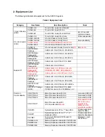
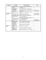
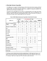
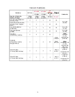


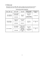

Table 4-2-4 Optional Boards
9.5” B+E
9.5” B+E
9.5”
B+E x 4
Hardware 9.5”
GW
19” KSU
19” KSU
19” KSU x
4
Network
ed KSUs
Number of Slot(s) for Interface
Package
2 Slots
w/ CPU
5 Slots
w/ CPU
6 Slots
w/o CPU
23 Slots
240 slots
Comments
CD-PVAA
(Conference Bridge)
2 5 6 23 32
CD-ETIA
(Switching Hub with Power over
Ethernet)
2 3 3 12 64
CD-CCTA
(CCIS Trunk Interface/Common
Channel Handler)
2 4 4 4 4
CD-RTB
(Router)
1 1 2 7 50
CD-VM00
(Voice Mail and Server)
1 1 1 1 1
Maximum of one
per system
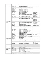
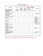
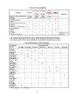
The following chart shows each main board and associated daughter board combinations.
The daughter boards that can be mounted on specific boards are indicated by a checkmark.
For example, the CD-LTA can have a PZ-2BRIA or the PZ-4COTF daughter board mounted.
Table 4-2-5 Daughter board Combination
Daughter Board
Controlling
Board
PZ-2BRIA PZ-4COTE PZ-4COTF
PZ-4COTG
PZ-4LCA PZ-8LCE
PZ-8DLCB
CD-LTA
(8 Digital/2
Single Line)
✔
✔
✔
✔
―
―
―
CD-LTB
(2 Single Line)
✔
✔
―
✔
―
―
―
CD-4COTA
(4 Loop Start)
―
✔
―
―
―
―
―
CD-4COTB
(4 Loop / GND
Start)
―
―
✔
―
―
―
―
CD-4COTC
(4 Loop Start)
―
―
―
✔
―
―
―
CD-4LCA
(4 Single Line
Interface)
―
―
―
―
✔
✔
―
CD-8LCA
(8 Single Line
Interface)
―
―
―
―
✔
✔
―
CD-8DLCA
(8 Digital
Station
Interface)
―
―
―
―
―
―
✔
CD-16DLCA
(16 Digital
Station
Interface)
―
―
―
―
―
―
―
CD-2BRIA
(2 Basic Rate
Interface)
✔
―
―
―
―
―
―
―
= Does not apply
✔
= Does apply
19


