


System Board 4-5
Upgrade Sockets
The system board has the following upgrade sockets:
!
processor socket
!
DIMM sockets.
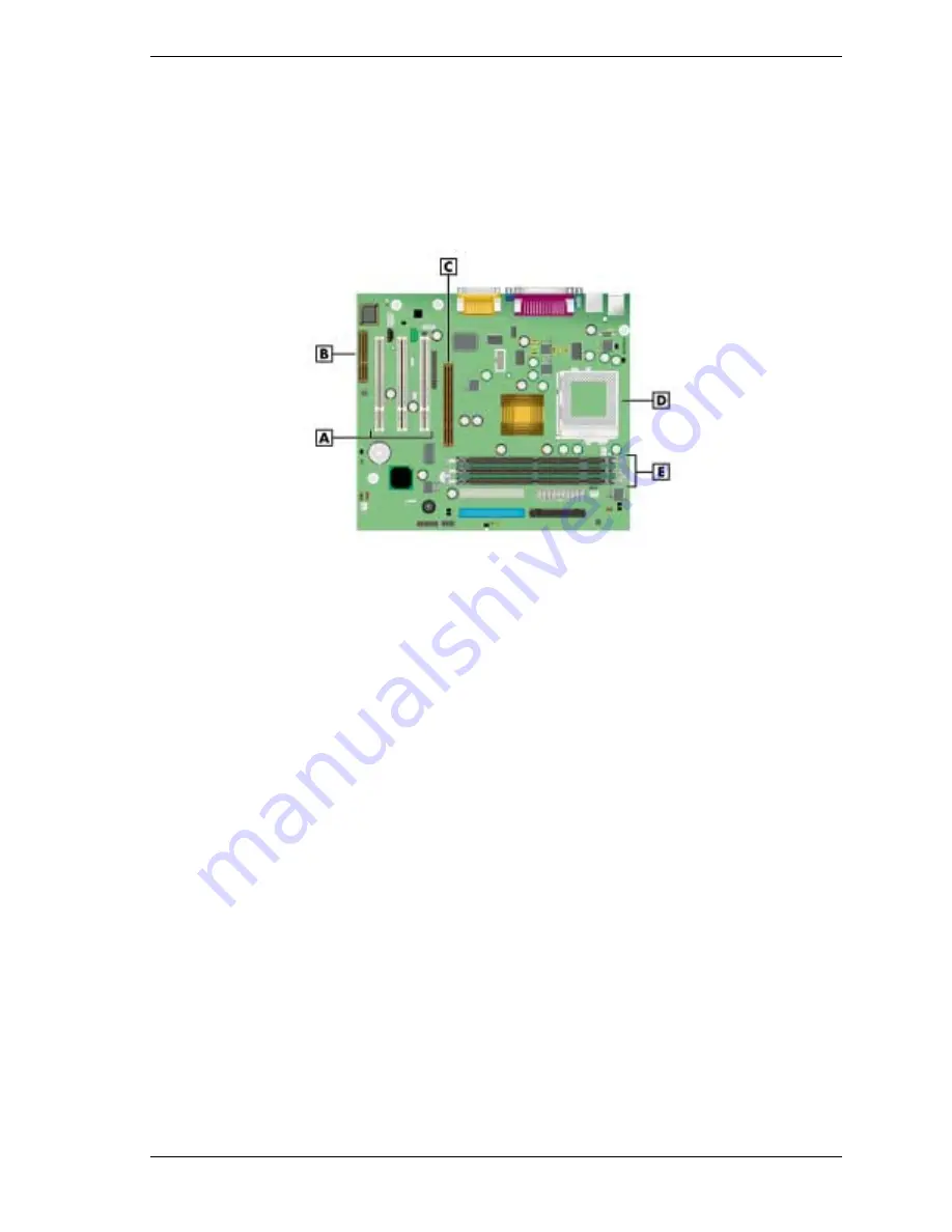
Upgrade Sockets on the System Board
A
– PCI Expansion Board Connectors
D
– Processor Socket
B
– CNR Board Connector
E
– DIMM Sockets
C
– AGP Board Connector
Processor Socket
The processor installs in a 370-pin socket (Socket 370) on the system board. The processor is
held in place in the socket by a locking lever attached to the socket and a removable retention
clip. The retention clip anchors both the processor and the processor heat sink to the Socket 370.
To remove or install a processor, see Section 3, “Disassembly and Reassembly.”
DIMM Sockets
Memory upgrades are installed into three memory module sockets on the system board. The
sockets support up to 512 MB of high-speed memory. The system supports 168-pin,
100/133-MHz SDRAM modules in 64-, 128-, and 256-MB unbuffered memory configurations.
Dual inline memory modules (DIMMs) are supported.
Use the following guidelines in selecting DIMM types:
!
memory can be installed in one, two, or three sockets, in any order
!
the size of the DIMMs can vary between sockets
!
single- and double-sided DIMMs are supported.
For sample memory configurations, see the table “Sample DIMM Upgrade Paths.”
To locate memory module sockets on the system board, see the previous figure, “Upgrade
Sockets on the System Board.”
To determine the memory needed for a memory upgrade, see “Checking System Memory.”
Summary of Contents for POWERMATE CT 815 - RELEASE NOTES
Page 13: ...1 System Overview Configurations Features Components Software...
Page 106: ...6 Preventive Maintenance System Cleaning Keyboard Cleaning Mouse Cleaning...
Page 109: ...7 Troubleshooting Checklist Diagnostics...
Page 118: ...8 NECC Information Services Service and Support Functions Technical Support...