background image

8

6

6. Installation and Connections

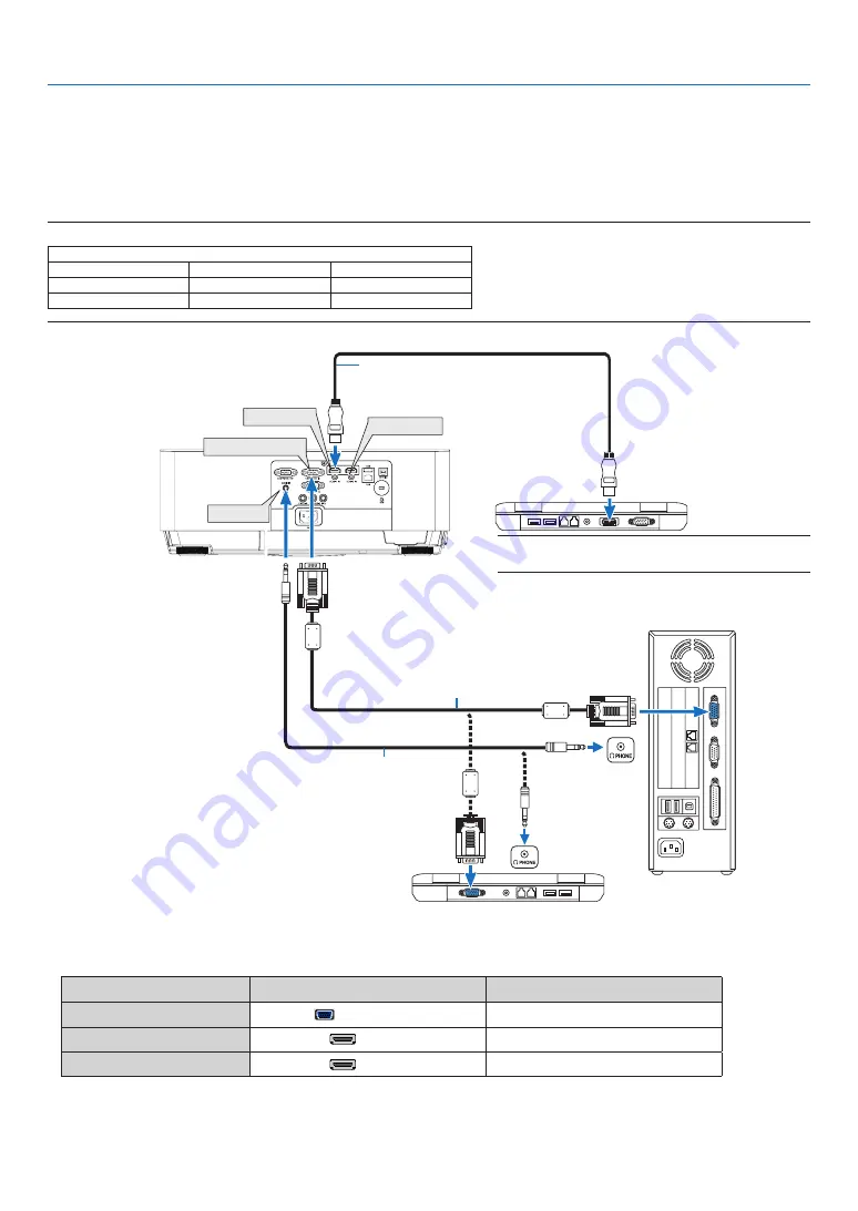
 Making Connections

NOTE: Signals supported by Plug & Play (DDC2)

INPUT

COMPUTER


IN

HDMI


1


IN

HDMI


2


IN

analog

digital

digital

Yes

Yes

Yes

• Select


the


source


name


for


its


appropriate


input


terminal


after


turning


on


the


projector.

Input


terminal

SOURCE


button


on


the


projector


cabinet

Button


on


the


remote


control

COMPUTER


IN


COMPUTER

(COMPUTER


1)

HDMI


1


IN


HDMI1

(HDMI


1)

HDMI


2


IN


HDMI2

(HDMI


2)

HDMI 1 IN

HDMI 2 IN

AUDIO IN

Computer cable (VGA) (supplied)
To mini D-Sub 15-pin terminal on the 

projector. It is recommended that you use 

a commercially available distribution  
amplifier if connecting a signal cable 
longer than the cable supplied.

Stereo mini-plug audio cable (not supplied)

HDMI cable (not supplied)
Use High Speed HDMI® Cable.

NOTE: For Mac, use a commercially available pin adapter 
(not supplied) to connect to your Mac’s video port.

Connecting Your Computer

Computer cables, HDMI can be used to connect to a computer. The connection cable is not enclosed with the projector.

Please


get ready a suitable cable for the connection.

COMPUTER IN

Summary of Contents for NP-UM383WL

Page 1: ...Projector UM383WL User s Manual Please visit our web site for User s Manual in the latest version https www nec display com dl en pj_manual lineup html Model No NP UM383WL ...

Page 2: ...ed for trademark rights in Japan the United States of America and other countries and areas Blu ray is a trademark of Blu ray Disc Association Ethernet is either a registered trademark or trademark of Fuji Xerox Co Ltd Android and Google Play are trademarks of Google Inc Other product names and logos mentioned in this user s manual may be the trademarks or registered trademarks of their respective...

Page 3: ...ORNIA RESIDENTS Handling the cables supplied with this product will expose you to lead a chemical known to the State of California to cause birth defects or other reproductive harm WASH HANDS AFTER HANDLING FCC Information for USA only WARNING The Federal Communications Commission does not allow any modifications or changes to the unit EXCEPT those specified by NEC Display Solutions of America Inc...

Page 4: ... must be in accordance with any local building codes Please consult your dealer for more information Do not install and store the projector in the below circumstances Failure to do so may cause of malfunction In powerful magnetic field In corrosive gas environment Outdoors WARNING Do not place any objects which are easily affected by heat in front of the projection window Doing so could lead to th...

Page 5: ...extensive therefore any kind of abnormal objects that can redirect light coming out of the lens can cause unpredictable outcome such as fire or injury to the eyes Do not place any objects which are easily affected by heat in front of a projector exhaust vent Doing so could lead to the object melting or getting your hands burned from the heat that is emitted from the exhaust Do not splash water ove...

Page 6: ...gh Altitude mode Set FAN MODE to HIGH ALTITUDE when using the projector at altitudes approximately 5500 feet 1700 meters or higher Using the projector at altitudes approximately 5500 feet 1700 meters or higher without setting to HIGH ALTITUDE can cause the projector to overheat and the protector could shut down If this happens wait a couple minutes and turn on the projector Using the projector at ...

Page 7: ...E the following terminals and functions will not work MONITOR OUT terminal AUDIO OUT terminal LAN functions Mail Alert function DDC CI Virtual Remote Tool Please refer to page 73 about details When NETWORK STANDBY has been set for STANDBY MODE and the LAN has been in link down condition for 3 minutes STANDBY MODE will transit into NORMAL automatically for the purpose to save the consumption power ...

Page 8: ...elect screen 13 Selecting a Source 14 Selecting the computer or video source 14 Adjusting the Picture Size and Position 15 Adjusting the vertical position of a projected image Lens shift 16 vi Focus 18 Zoom 19 Digital Zoom 20 Adjust the Tilt Foot 21 Correcting Keystone Distortion KEYSTONE 22 Optimizing Computer Signal Automatically 24 Adjusting the Image Using Auto Adjust 24 Turning Up or Down Vol...

Page 9: ...Viewer 43 Projecting images stored in a USB memory device 45 5 Using On Screen Menu 51 HDMI1 and HDMI2 56 COMPUTER 56 VIDEO 56 USB A 56 LAN 56 Menu Descriptions Functions ADJUST 57 PICTURE 57 IMAGE OPTIONS 60 AUDIO 64 GENERAL 65 MENU 68 INSTALLATION 69 OPTIONS 1 71 OPTIONS 2 73 Setting up the Projector for a Wired LAN Connection WIRED LAN 76 USAGE TIME 77 CONNECTION 78 Using the Menus 51 Menu Desc...

Page 10: ...onnecting Your DVD Player or Other AV Equipment 89 Connecting Component Input 90 Connecting HDMI Input 91 Connecting to a Wired LAN 92 Maintenance 93 Cleaning the Filters 93 Cleaning the Projection Window 95 Cleaning the Cabinet 95 Appendix 96 Troubleshooting 96 Cabinet Dimensions 104 Pin Assignments of D Sub COMPUTER Input Terminal 105 Compatible Input Signal List 106 PC Control Codes and Cable C...

Page 11: ...er Please save the original box and packing materials if you ever need to ship your projector Power cord 7N080236 7N080242 Computer cable VGA 7N520089 NEC Projector CD ROM User s manual PDF 7N952943 Important Infomation 7N8R0231 Remote control Batteries AAA 2 7N901053 Quick Setup Guide 7N8R0241 For North America only Limited warranty ...

Page 12: ...s ECO MODE is set to AUTO ECO NORMAL or ECO The amount of CO2 emission reduction will be displayed in the confirmation message at the time of power off and in the INFO of the on screen menu Wide range of input terminals HDMI 2 The projector is equipped with a variety of input terminals HDMI 2 Computer analog Video HDMI input terminal on this product supports HDCP Compatible with the MultiPresenter...

Page 13: ...r on At the beginning of each section of the manual you ll find an overview If the section doesn t apply you can skip it INTELLIGENT CONNECTION It enables easily to connect your projector to computers or smartphones on which the application software MultiPresenter has been installed by inputting PIN code Convenient utility software User Supportware This projector supports our utility software NaVi...

Page 14: ...s exhausted from here Stereo Speaker 10W Security chain opening Attach an anti theft device The security chain opening accepts security wires or chains up to 0 18 inch 4 6 mm in diameter Remote Sensor page 9 Indicators page 6 Controls page 6 Lens shift cover page 16 Focus Ring page 18 Zoom Lever page 19 ...

Page 15: ...s the MicroSaver Security System Rear Foot page 21 Built in Security Slot AC Input Connect the supplied power cord s three pin plug here and plug the other end into an active wall outlet page 11 Terminal Panel page 7 Intake Vent Filter Cover page 93 ...

Page 16: ...5 2 POWER Indicator page 11 12 25 96 3 STATUS Indicator page 96 4 LIGHT Indicator page 96 5 ECO Button page 28 6 SOURCE Button page 14 7 AUTO ADJ Button page 24 8 MENU Button page 51 9 Volume Buttons Keystone Buttons page 22 24 30 51 10 ENTER Button page 51 11 EXIT Button page 51 2 3 4 ...

Page 17: ...e only 6 COMPUTER OUT Terminal Mini D Sub 15 Pin page 88 7 AUDIO OUT Mini Jack Stereo Mini page 88 8 VIDEO IN Terminal RCA page 89 9 AUDIO IN L R RCA page 89 10 LAN Port RJ 45 page 92 11 USB Port Type A For USB memory page 45 12 PC CONTROL Port D Sub 9 Pin page 107 Use this port to connect a PC or control system This enables you to control the projector using serial communication protocol If you a...

Page 18: ... 15 ID SET Button page 70 16 Numeric Keypad Button CLEAR Button page 70 17 FREEZE Button page 26 18 AV MUTE Button page 26 19 MENU Button page 51 20 EXIT Button page 51 21 Button page 51 22 ENTER Button page 51 23 D ZOOM Button page 27 24 MOUSE L CLICK Button This button does not work on this series of projectors 25 MOUSE R CLICK Button This button does not work on this series of projectors 26 PAG...

Page 19: ...ng the remote control for a long time remove the batteries Ensure that you have the batteries polarity aligned correctly Do not use new and old batteries together or use different types of batteries together Dispose of used batteries according to your local regulations Operating Range for Wireless Remote Control The infrared signal operates by line of sight up to a distance of about 22 feet 7 m an...

Page 20: ...tor page 12 Step 3 Selecting a source page 14 Step 4 Adjusting the picture size and position page 15 Correcting keystone distortion KEYSTONE page 22 Step 5 Adjusting a picture and sound Optimizing a computer signal automatically page 24 Turning up or down volume page 24 Step 6 Making a presentation Step 7 Turning off the projector page 25 Step 8 When Moving the Projector page 25 2 Projecting an Im...

Page 21: ...cord to the projector First connect the supplied power cord s three pin plug to the AC IN of the projector and then connect the other plug of the supplied power cord in the wall outlet The projector s power indicator will start blinking orange This will apply for both indicators when NORMAL is selected for STANDBY MODE See the Power Indicator section page 96 CAUTION Parts of the projector may beco...

Page 22: ...me ready to use TIP When the message Projector is locked Enter your password is displayed it means that the SECURITY feature is turned on page 34 After you turn on your projector ensure that the computer or video source is turned on NOTE When no input signal is present the no signal guidance is displayed factory menu setting Standby Blinking Power On page 96 Blinking orange light Blinking blue lig...

Page 23: ...ling to do so could result in no power to the projector There will be no stand by LED Should this happen unplug the power cord and plug it in again Turn on the main power If one of the following things happens the projector will not turn on If the internal temperature of the projector is too high the projector detects abnormal high temperature In this condition the projector will not turn on to pr...

Page 24: ...ss the MENU button The menu will be displayed 2 Press the button twice to select SETUP and the button or the ENTER button to select GENERAL 3 Press the button four times to select OPTIONS 2 4 Press the button five times to select DEFAULT SOURCE SE LECT and press the ENTER button The DEFAULT SOURCE SELECT screen will be displayed page 74 5 Select a source as the default source and press the ENTER b...

Page 25: ... picture size and position In this chapter drawings and cables are omitted for clarity Adjusting the projected image s vertical and horizontal position Lens shift page 16 Adjusting the focus Focus ring page 18 Finely adjusting the size of an image Zoom lever page 19 Adjusting the throw angle the height of an image Tilt foot page 21 Correcting the keystone distortion Keystone page 22 ...

Page 26: ...justment with an image Turn the lens shift dials clockwise or counterclockwise Vertical dial Turn this clockwise or counterclockwise to adjust the projection position in the vertical direction Horizontal dial Turn this clockwise or counterclockwise to adjust the projection position in the horizontal direction Stopper Open with the cover s stopper pushed forward The lens shift cover cannot be remov...

Page 27: ... the CEILING FRONT projection see page 84 Height of projected image Width of projected image Description of symbols V indicates vertical height of the projected image H indicates horizontal width of the projected image 3 Close the lens shift cover Insert the cover s 2 two hooks into the grooves in the projector then close the cover Hook Groove 3 V 3 V 2 H 100 H 100 V 2 H ...

Page 28: ...ed Rotate the Focus ring until you obtain the best focus 2 Focus ring 3 Close the lens shift cover Insert the cover s 2 two hooks into the grooves in the projector then close the cover Hook Groove NOTE It is recommended to perform focus adjustment after the projector has been projecting for more than 30 minutes in TEST PATTERN mode About TEST PATTERN please refer to page 71 ...

Page 29: ... is a spring buckle which can be opened by gently pressing down The zoom cover cannot be removed 2 Spring buckle Zoom lever 3 Close the zoom cover Spring buckle Adjust the Zoom lever left or right until you obtain the best zoom Press down on the cover and hear a ticking sound to close the cover ...

Page 30: ...n the remote control The DIGITAL ZOOM bar will be displayed 2 Press the or button to finely zoom in or out 3 After completing the adjustment press the ENTER button The DIGITAL ZOOM bar will be closed NOTE This feature allows you to electronically fine adjust the image size on the screen This feature can not be used when USB A or LAN is selected as an input terminal ...

Page 31: ...t foot to adjust the angle to project If keystone distortion is appeared adjust it either by the button on the cabinet or keystone button on the remote control NOTE Do not extend the tilt foot beyond its height limit 18 mm 0 7 inches Doing so may cause the tilt foot to come out of the projector Do not use the tilt foot for purposes other than originally intended Misuses such as using the tilt foot...

Page 32: ...NERSTONE If the value of either CONERSTONE or PINCUSHION has corrected KEYSTONE HORIZONTAL and KEYSTONE VERTICAL are disabled In this case RESET the corrected values and restart to correct distortion 1 Press the button on the projector cabinet The Keystone screen will be displayed on the screen Press the KEYSTONE button when using the remote control See page for PINCUSHION See page for CORNERSTONE...

Page 33: ...n The Keystone screen will disappear To perform Keystone correction again press the button to display the Keystone screen and repeat above steps 1 to 6 To return the keystone adjustments to default 1 Press the button to select RESET and press the ENTER button 2 Press the or button to select YES and press the ENTER button The adjustments will be reset All the adjustments for all the five items will...

Page 34: ...eration cannot optimize the computer signal try to adjust HORIZONTAL VERTICAL CLOCK and PHASE manually page 60 61 Turning Up or Down Volume Sound level from the speaker or audio output can be adjusted TIP When no menus appear the and buttons on the projector cabinet work as a volume control NOTE Volume control is not available with the or button when an image is magnified by using the D ZOOM butto...

Page 35: ...N Parts of the projector may become temporarily heated if the projector is turned off with the POWER button or if the AC power supply is disconnected during normal projector operation Use caution when picking up the projector NOTE While the power indicator is blinking blue in short cycles the power cannot be turned off Do not disconnect the AC power supply to the projector within 10 seconds after ...

Page 36: ...E Even though the image is turned off the menu still remains on the screen Sound from the AUDIO OUT jack Stereo mini can be turned off Even when the power saving function works the light power may be restored to its original level temporarily Freezing a Picture Press the FREEZE button to freeze a picture Press again to resume motion NOTE The image is frozen but the original video is still playing ...

Page 37: ... The image will be magnified or demagnified at the center of the screen Displaying the menu will cancel the current magnification Magnifying a Picture You can enlarge the picture up to four times NOTE The maximum magnification may be less than four times depending on the signal To do so 1 Press the D ZOOM button to magnify the picture To move the magnified image use the or button ...

Page 38: ...eaf symbol at the bottom of the menu shows the current selection of ECO mode NOTE The ECO MODE can be changed by using the menu Select SETUP GENERAL LIGHT MODE ECO MODE The light hours used can be checked in USAGE TIME Select INFO USAGE TIME The projector is always in NORMAL for 10 seconds after the light is turned on The light condition will not be affected even when ECO MODE is changed After a l...

Page 39: ...after the time of power on and the time of power off The CARBON SAVINGS SESSION message will be displayed in the POWER OFF ARE YOU SURE message at the time of power off TIP The formula as shown below is used to calculate the amount of CO2 emission reduction Amount of CO2 emission reduction Power consumption in OFF for ECO MODE Power consumption in AUTO ECO NORMAL ECO for ECO MODE CO2 conversion fa...

Page 40: ...TONE HORIZONTAL and KEYSTONE VERTICAL are disabled In this case RESET the corrected values and restart to correct distortion Cornerstone 1 Press the KEYSTONE button with no menu displayed The KEYSTONE screen will be displayed Press the KEYSTONE button when using the remote control See page for PINCUSHION 2 Press the button to select CORNERSTONE and press the ENTER button The drawing shows the uppe...

Page 41: ...move the projected image frame as shown on the example 8 Press the ENTER button 9 Use the button to select another icon which points in the direction On the Cornerstone adjustment screen select EXIT or press the EXIT button on the remote control The confirmation screen is displayed 10 Press the or button to highlight the OK and press the ENTER button This completes the Cornerstone correction Selec...

Page 42: ...HT or PINCUSHION TOP BOTTOM 3 Press the or button to correct distortion NOTE The PINCUSHION LEFT RIGHT or PINCUSHION TOP BOTTOM item is not available when KEYSTONE HORIZONTAL KEYSTONE VERTICAL or COR NERSTONE is activated Before performing correction set the lens shift to the center position 4 Press the EXIT when PINCUSHION adjustment is completed NOTE Even when the projector is turned on the last...

Page 43: ...press ENTER button Confirmation message is displayed on 2 Move the cursor onto YES using either or button and then press the ENTER NOTE All adjusted values set in the KEYSTONE adjustment are reset to initial values TIP Adjustable range of the KEYSTONE and the CORNERSTONE Horizontal Direction Vertical Direction CORNERSTONE Approx 10 Max Approx 10 Max KEYSTONE Adjustable range may be narrower depend...

Page 44: ... menu To enable the Security function 1 Press the MENU button The menu will be displayed 2 Press the button twice to select SETUP and press the button or the ENTER button to select GEN ERAL 3 Press the button to select INSTALLATION 4 Press the button three times to select SECURITY and press the ENTER button The OFF ON menu will be displayed 5 Press the button to select ON and press the ENTER butto...

Page 45: ...n enabled To turn on the projector when SECURITY is enabled 1 Press the POWER button The projector will be turned on and display a message to the effect that the projector is locked 2 Press the MENU button 3 Type in the correct keyword and press the ENTER button The projector will display an image NOTE The security disable mode is maintained until the main power is turned off or unplugging the pow...

Page 46: ... button The SECURITY KEYWORD screen will be displayed 4 Type in your keyword and press the ENTER button When the correct keyword is entered the SECURITY function will be disabled NOTE If you forget your keyword contact your dealer Your dealer will provide you with your keyword in exchange for your request code Your request code is displayed in the Keyword Confirmation screen In this example NB52 Y...

Page 47: ...s of your network Should this happen consult your network administrator The projector may not respond if its buttons are repeatedly pressed in rapid intervals Should this happen wait a moment and repeat If you still can t get any response turn off and back on the projector If the PROJECTOR NETWORK SETTINGS screen does not appear in the web browser press the Ctrl F5 keys to refresh your web browser...

Page 48: ...ing by specifying http pj nec co jp index html for the address or the entry column of the URL Example 2 When the IP address of the projector is 192 168 73 1 access is gained to the network setting by specifying http 192 168 73 1 index html for the address or the entry column of the URL PROJECTOR ADJUSTMENT POWER This controls the power of the projector ON Power is switched on OFF Power is switched...

Page 49: ...nding on the signal being input to the projector page 59 SOURCE SELECT This switches the input terminal of the projector HDMI1 Switches to the HDMI 1 IN terminal HDMI2 Switches to the HDMI 2 IN terminal COMPUTER Switches to the COMPUTER IN terminal VIDEO Switches to the VIDEO IN terminal USB A Switches to the data on the USB memory device PROJECTOR STATUS This displays the condition of the project...

Page 50: ...DE PIN CODE For the case ONE TIME is selected as PIN TYPE automatically created PIN CODE is displayed on disabled to input For the case STATIC is selected as PIN TYPE input random 4 digits number as PIN CODE Select if you use the PIN CODE as a security password for connecting to the Multi Presenter application For using the PIN code as a security password add a check mark into the square UTILIZE P...

Page 51: ...RESET is done from the menu HOST NAME Enter the hostname of the network connected to the projector A host name must be 16 or less ALERT MAIL ALERT MAIL English only This option will notify your computer of light replace time or error messages via e mail when using wired LAN Placing a checkmark will turn on the Alert Mail feature Clearing a checkmark will turn off the Alert Mail feature Sample of a...

Page 52: ...e the device and download the appropriate Device Discovery Module from an AMX server Placing a checkmark will enable detecting the projector from AMX Device Discovery Clearing a checkmark will disable detecting the projector from AMX Device Discovery What is PJLink PJLink is a standardization of protocol used for controlling projectors of different manufacturers This standard protocol is establish...

Page 53: ...able presentations can be conducted simply with the projector Supported graphic format is JPEG The Viewer displays the thumbnail screen JPEG Exif only on which you can jump to any specifi image you wish to project There are two ways of playback for slideshow manual playback and auto playback The interval time can be changed in auto playback The order of displaying images can be set by name date or...

Page 54: ...y in your computer refer to the document or help file that comes with your Windows We do not warrant that the USB port of the projector will support all USB memories in the market Supported images Supported file format for Viewer are as follows We do not warrant all the images are supported for Viewer Images other than mentioned in the table may not be supported Image type Extension Description JP...

Page 55: ...rom the projector page 47 Exiting the Viewer page 47 Preparation Before starting the Viewer store images to the USB memory using your computer Starting the Viewer 1 Turn on the projector page 12 2 Insert the USB memory into the USB port of the projec tor Do not remove the USB memory from the projector while it s LED flashes Doing so may corrupt the data 3 Press the SOURCE button on the projector c...

Page 56: ...ton to select the next slide The slide on the right will be displayed The or button can be used to select the next right slide or the previous left slide in the thumbnail screen Pressing the MENU button during display of the thumbnail screen the slide screen or the slideshow screen will display the toolbar The toolbar is used to select or rotate an slide page 50 8 Press the EXIT button when the to...

Page 57: ...rojector may not operate correctly If this happens turn off the projector and unplug the power cord Wait 3 minutes then connect the power cord and turn on the projector Exiting the Viewer 1 Press the MENU button with the slide screen or the thumbnail screen displayed The control bar or the pop up menu will be displayed 2 Press the MENU button again The on screen menu will be displayed 3 Select a s...

Page 58: ...B memory has folders 7 Page up Page down icon This icon shows further folders or image files are available in the next previous page Use the button to go to the next previous row The PAGE or PAGE on the remote control is used to go to the next or previous page directly 8 Thumbnail toolbar This toolbar is used in the thumbnail screen Pressing the MENU button will display this toolbar page 49 9 Slid...

Page 59: ... displayed Press the MENU button again to close the SOURCE list Thumbnail toolbar Menu Options Description 1 Back Goes back to the previous image When the cursor reaches the top left of the screen it will go to the previous page 2 Forward Goes to the next image When the cursor reaches the bottom right of the screen it will go to the next page 3 Display Closes the menu and returns to the thumbnail ...

Page 60: ...ise 4 Counter clockwise rotation Close the menu and rotate the image 90 counter clockwise Slideshow toolbar Menu Options Description 1 Stop Closes the menu and changes to the slide screen 2 Back Goes back to the previous image 3 Forward Goes to the next image 4 Interval Specifie interval time when playing back the slides 5 Repeat Repeats to play back the images in the folder Returns to the thumbna...

Page 61: ...projector cabinet to select the item you want to adjust or set You can use the buttons on the remote control or the projector cabinet to select the tab you want 5 Press the ENTER button on the remote control or the projector cabinet to display the submenu window 6 Adjust the level or turn the selected item on or off by using the buttons on the remote control or the projector cabinet Changes are st...

Page 62: ...n option in a dialog box Source Indicates the currently selected source Off Timer remaining time Indicates the remaining countdown time when the OFF TIMER is preset Slide bar Indicates settings or the direction of adjustment ECO mode symbol Indicates ECO MODE is set Key Lock symbol Indicates the CONTROL PANEL LOCK is enabled Thermometer symbol Indicates the ECO MODE is forcibly set to NORMAL mode ...

Page 63: ...EXT3 TEXT4 OFF OFF 0 30 1 00 2 00 4 00 8 00 12 00 16 00 ENGLISH ENGLISH DEUTSCH FRANÇAIS ITALIANO ESPAÑOL SVENSKA 日本語 DANSK PORTUGUÊS ČEŠTINA MAGYAR POLSKI NEDERLANDS SUOMI NORSK TÜRKÇE РУССКИЙ Ελληνικά 简体中文 한국어 TIẾNG ViỆT ROMÂNĂ HRVATSKI БЪЛГАРСКИ INDONESIA ไทย 繁體中文 RESET WALL COLOR LIGHT MODE ECO MODE ADJUST CONSTANT BRIGHTNESS BALANCE VOLUME SETUP GENERAL DIGITAL ZOOM KEYSTONE KEYSTONE HORIZONT...

Page 64: ...PUTER LAN LAN COMPUTER ON OFF ON NORMAL NORMAL NETWORK STANDBY OFF OFF ON OFF OFF ON STANDBY NORMAL 1 00 NETWORK STANDBY 0 15 OFF 0 05 0 10 0 15 0 20 0 30 1 00 LAST LAST AUTO HDMI1 HDMI2 COMPUTER VIDEO USB A LAN ENABLE DISABLE ENABLE DHCP ON AUTO DNS ON DHCP IP ADDRESS SUBNET MASK GATEWAY AUTO DNS DNS WIRED LAN WIRED LAN SETTINGS RECONNECT BEEP OPTIONS 2 STANDBY MODE DIRECT POWER ON AUTO POWER ON ...

Page 65: ...TOR NAME PIN CODE IP ADDRESS MAC ADDRESS Menu Item USAGE TIME LIGHT HOURS USED FILTER HOURS USED TOTAL CARBON SAVINGS TOTAL COST SAVINGS SOURCE 1 SOURCE NAME SOURCE INDEX HORIZONTAL FREQUENCY VERTICAL FREQUENCY SYNC TYPE SYNC POLARITY SCAN TYPE SOURCE 2 SIGNAL TYPE VIDEO TYPE BIT DEPTH VIDEO LEVEL WIRED LAN IP ADDRESS SUBNET MASK GATEWAY CONTROL ID when CONTROL ID is set CURRENT SIGNAL RESET ALL D...

Page 66: ...nected to your COMPUTER input terminal signal NOTE When the component input signal is connected to the COMPUTER IN terminal select COMPUTER VIDEO Selects what is connected to your VIDEO input VCR DVD player or document camera USB A This feature enables you to make presentations using a USB memory that contains slides page 43 4 Using the Viewer LAN Selects a signal from the LAN port RJ 45 ...

Page 67: ...brightly lit room PRESENTATION Recommended for making a presentation using a PowerPoint fil VIDEO Recommended for typical TV program viewing MOVIE Recommended for movies GRAPHIC Recommended for graphics sRGB Standard color values DICOM SIM Recommended for DICOM simulation format NOTE The DICOM SIM option is for training reference only and should not be used for actual diagnosis DICOM stands for Di...

Page 68: ...not available when DICOM SIM is selected for DETAIL SETTINGS Selecting Screen Size for DICOM SIM SCREEN SIZE This function will perform gamma correction appropriate for the screen size LARGE For screen size of 110 MEDIUM For screen size of 90 SMALL For screen size of 70 NOTE This function is available only when DICOM SIM is selected for DETAIL SETTINGS Adjusting Color Temperature COLOR TEMPERATURE...

Page 69: ... level or the back raster intensity SHARPNESS Controls the detail of the image COLOR Increases or decreases the color saturation level HUE Varies the color level from green to blue The red level is used as reference Input signal CONTRAST BRIGHTNESS SHARPNESS COLOR HUE COMPUTER HDMI RGB Yes Yes Yes No No COMPUTER HDMI COMPONENT Yes Yes Yes Yes Yes VIDEO Yes Yes Yes Yes Yes USB A Yes Yes Yes No No Y...

Page 70: ...E CLOCK Use this item to fine tune the computer image or to remove any vertical banding that might appear This function PHASE Use this item to adjust the clock phase or to reduce video noise dot interference or cross talk This is evident when part of your image appears to be shimmering Use PHASE only after the CLOCK is complete ...

Page 71: ... signal The next time you project the signal with the same resolution horizontal and vertical frequency its adjustments will be called up and applied To delete adjustments stored in memory from the menu you select RESET CURRENT SIGNAL or ALL DATA and reset the adjustments Selecting Overscan Percentage OVERSCAN Select overscan percentage AUTO 0 5 and 10 for signal Projected image Overscaned by 10 N...

Page 72: ...ending on its signal If this occurs select the appropriate aspect ratio from the following 4 3 The image is displayed in 4 3 aspect ratio 16 9 The image is displayed in 16 9 aspect ratio 15 9 The image is displayed in 15 9 aspect ratio 16 10 The image is displayed in 16 10 aspect ratio LETTERBOX The image of a letterbox signal is stretched equally in the horizontal and vertical direc tions to fi t...

Page 73: ...OTE To display a letterbox signal properly select LETTERBOX NOTE To display a squeezed signal properly select 16 9 TIP Image position can be adjusted vertically using POSITION when the 16 9 15 9 or 16 10 aspect ratios are selected The term letterbox refers to a more landscape oriented image when compared to a 4 3 image which is the standard aspect ratio for a video source The letterbox signal has ...

Page 74: ...ning Up or Down Sound Adjusts the volume of the projector speaker and AUDIO OUT Stereo Mini Jack TIP When no menus appear the and buttons on the projector cabinet and the VOL buttons on the remote control work as a volume control page 24 ...

Page 75: ...e 22 PINCUSHION LEFT RIGHT Corrects pincushion distortion at the left or right side page 32 PINCUSHION TOP BOTTOM Corrects pincushion distortion at the top or bottom side page 32 CORNERSTONE Fits a projected image within the border of the screen easily by align the four corner of an image to the ones of the screen page 30 RESET Returns all the above items to the factory preset values TIP The maxim...

Page 76: ... to OFF and CONSTANT BRIGHT NESS is set to OFF CONSTANT BRIGHTNESS OFF CONSTANT BRIGHTNESS mode will be canceled ON Maintains 66 brightness of the factory default setting NOTE CONSTANT BRIGHTNESS mode is a function used to maintain the brightness at a constant level Color will not be fixed TIP Brightness normally decreases with use but by selecting CONSTANT BRIGHTNESS mode the projector automatica...

Page 77: ...or closed caption within the screen Using Off Timer OFF TIMER 1 Select your desired time between 30 minutes and 16 hours OFF 0 30 1 00 2 00 4 00 8 00 12 00 16 00 2 Press the ENTER button on the remote control 3 The remaining time starts counting down 4 The projector will turn off after the countdown is complete NOTE To cancel the preset time set OFF for the preset time or turn off the power When t...

Page 78: ...he screen regardless of its selection Your setting will not be affected even when RESET is done from the menu OFF 100 H 500 H 1000 H 2000 H NOTE Your setting will not be affected even when RESET is done from the menu Selecting Interval Time for Filter Message FILTER MESSAGE This option allows you to select the time preference between displaying the message for cleaning the filters Clean the filter...

Page 79: ...ROL PANEL LOCK function NOTE This CONTROL PANEL LOCK does not affect the remote control functions When the control panel is locked pressing and holding the SOURCE button on the projector cabinet for about 10 seconds will change the setting to OFF TIP When the CONTROL PANEL LOCK is turned on a key lock icon will be displayed at the bottom right of the menu Enabling Security SECURITY This feature tu...

Page 80: ...on In this case the buttons on the projector cabinet can be used Your setting will not be affected even when RESET is done from the menu Pressing and holding the ENTER button on the projector cabinet for 10 seconds will display the menu for canceling the Control ID Assigning or Changing the Control ID 1 Turn on the projector 2 Press the ID SET button on the remote control The CONTROL ID screen wil...

Page 81: ...ion when using the projector at altitudes approximately 5500 feet 1700 meters or higher When you wish to cool down the temperature inside the projector quickly select HIGH NOTE It is recommended that you select High speed mode if you use the projector non stop for consecutive days Set FAN MODE to HIGH ALTITUDE when using the projector at altitudes approximately 5500 feet 1700 meters or higher Usin...

Page 82: ...or a telecine signal OFF Select this option if there is any jitter or artifacts in video ON Default standard setting NOTE This feature is not available for HDTV progressive and computer signals VIDEO LEVEL Select AUTO to automatically detect video level If automatic detection may not work well select NORMAL to disable the ENHANCED feature of your HDMI equipment or select ENHANCED to improve image ...

Page 83: ...isplayed in grey and 0 15 is selected auto matically When STANDBY MODE NETWORK STANDBY is selected When NETWORK SERVICE AMX SETTINGS ENABLE is selected When the signal is input to the computer HDMI 1 IN or HDMI 2 IN terminals NOTE Even when NORMAL is selected for STANDBY MODE power on or off can be done by using the PC CONTROL port The power consumption in the standby mode will not be included in ...

Page 84: ...WER OFF When this option is selected you can enable the projector to automatically turn off at the selected time 0 05 0 10 0 15 0 20 0 30 1 00 if there is no signal received by any input or if no operation is performed Selecting Default Source DEFAULT SOURCE SELECT You can set the projector to default to any one of its inputs each time the projector is turned on LAST Sets the projector to default ...

Page 85: ...or CARBON METER The initial setting are as follows US Dollar 0 11 kWh EU Euro 0 19 kWh Japanese Yen 20 kWh Chinese Yuan 0 48 kWh The initial settings for US dollar EU Euro and Japanese Yen are based on Energy Prices and Taxes second quarter 2010 published by OECD The initial setting for Chinese Yuan is based on Chinese Data File 2010 published by JETRO ...

Page 86: ... turned on SETTINGS DHCP ON IP address subnet mask and gateway will be automatically assigned to the projector from your DHCP server OFF Specify IP address subnet mask and gateway assigned by your network administrator IP ADDRESS Set your IP address of the network connected to the projector SUBNET MASK Set your subnet mask number of the network connected to the projector GATEWAY Set the default ga...

Page 87: ...control will show the INFO menu items USAGE TIME LIGHT HOURS USED H FILTER HOURS USED H TOTAL CARBON SAVINGS kg CO2 TOTAL COST SAVINGS TOTAL CARBON SAVINGS This displays the estimated carbon saving information in kg The carbon footprint factor in the carbon saving calculation is based on the OECD 2008 Edition page 29 SOURCE 1 SOURCE INDEX VERTICAL FREQUENCY SYNC POLARITY SOURCE NAME HORIZONTAL FRE...

Page 88: ...78 5 Using On Screen Menu SOURCE 2 VIDEO TYPE VIDEO LEVEL WIRED LAN SUBNET MASK MAC ADDRESS SIGNAL TYPE BIT DEPTH IP ADDRESS GATEWAY CONNECTION PROJECTOR NAME WIRED LAN PIN CODE IP ADDRESS ...

Page 89: ...79 5 Using On Screen Menu VERSION FIRMWARE Version DATA Version OTHERS PROJECTOR NAME HOST NAME MODEL NO SERIAL NUMBER CONTROL ID when CONTROL ID is set ...

Page 90: ...SE and OVERSCAN ALL DATA Reset all the adjustments and settings for all the signals to the factory preset All items can be reset EXCEPT LANGUAGE BACKGROUND ORIENTATION FILTER MESSAGE SECU RITY COMMUNICATION SPEED CONTROL ID STANDBY MODE FAN MODE CARBON CONVERT CURRENCY CURRENCY CONVERT LIGHT HOURS USED FILTER HOURS USED TOTAL CARBON SAVINGS and WIRED LAN NOTE Elapsed time of the filter use will no...

Page 91: ...7 20 7 527 100 2540 84 8 2154 53 0 1346 15 6 397 68 6 1743 10 0 255 23 0 585 110 2794 93 3 2369 58 3 1481 16 8 428 75 1 1909 12 3 313 25 3 643 120 3048 101 8 2585 63 6 1615 18 1 458 81 7 2074 14 6 371 27 6 701 130 3302 110 2 2800 68 9 1750 19 3 489 88 2 2239 16 9 429 29 9 759 H1 H2 L1 L2 Diagonal Width Height Wide Screen Size Thefurtheryourprojectorisfromthescreenorwall thelargertheimage Theminimu...

Page 92: ...he ground you can be injured and the projector severely damaged Do not use the projector where temperatures vary greatly The projector must be used at temperatures between 41 F 5 C and 104 F 40 C Eco mode selected automatically at 95 F to 104 F 35 C to 40 C Do not expose the projector to moisture dust or smoke This will harm the screen image Ensure that you have adequate ventilation around your pr...

Page 93: ...wer edge of screen with tilt feet screwed in H L Projector bottom Center of screen inch mm inch mm inch mm inch mm inch mm 10 9 276 13 1 333 12 0 305 16 2 410 17 0 432 11 9 303 14 5 368 13 2 335 18 4 468 19 4 493 13 0 330 15 8 402 14 4 366 20 7 527 21 8 554 14 0 357 17 2 437 15 6 397 23 0 585 24 2 615 15 1 383 18 6 472 16 8 428 25 3 643 26 6 676 16 1 410 20 0 507 18 1 458 27 6 701 29 0 738 17 2 43...

Page 94: ...w illustrated range blur and shade may appear around ends of projected image Legend V Vertical refers to the screen height and H Horizontal refers to the screen width The lens shift range is expressed as a ratio of height and width respectively Lens shifting range Vertical direction 3 Horizontal direction 2 3 V 3 V 2 H 100 H Width of projected image 100 V Height of projected image 2 H 3 V 3 V 2 H ...

Page 95: ... 53 0 134 6 cm Adjustment range in the vertical direction the projected image can be moved upwards 0 03 53 134 6 cm 1 6 4 06 cm when the lens is at the center position Adjustment range in the horizontal direction the projected image can be moved to the left or right 0 02 84 8 215 4 cm 1 7 4 27 cm Figures differ by several because the calculation is approximate ...

Page 96: ...DMI 2 IN AUDIO IN Computer cable VGA supplied To mini D Sub 15 pin terminal on the projector It is recommended that you use a commercially available distribution amplifier if connecting a signal cable longer than the cable supplied Stereo mini plug audio cable not supplied HDMI cable not supplied Use High Speed HDMI Cable NOTE For Mac use a commercially available pin adapter not supplied to connec...

Page 97: ... a DVI signal When the computer has a DVI output terminal use a commercially available converter cable to connect the com puter to the projector s HDMI 1 or HDMI 2 input terminal only digital video signals can be input HDMI 1 IN HDMI 2 IN NOTE When Viewing a DVI Digital Signal Turn off the power of the computer and projector before connecting When a video deck is connected via a scan converter etc...

Page 98: ...pped In this case pull out the computer cable and set it back after inputting video signal Monitor out and sleep mode The COMPUTER OUT terminal will not work when NORMAL is selected for STANDBY MODE The COMPUTER OUT terminal will work only in the sleep mode Applying a signal from the COMPUTER IN terminal will put the projector in the sleep mode which allows you to use the COMPUTER OUT terminal and...

Page 99: ...he source name for its appropriate input terminal after turning on the projector Input terminal SOURCE button on the projector cabinet Button on the remote control VIDEO IN VIDEO VIDEO NOTE Refer to your VCR owner s manual for more information about your equipment s video output requirements NOTE An image may not be displayed correctly when a Video source is played back in fast forward or fast rew...

Page 100: ...l be automatically displayed If not from the menu select SETUP OPTIONS 1 SIGNAL SELECT COMPUTER and then place a check mark in the Component radio button Select the source name for its appropriate input terminal after turning on the projector Input terminal SOURCE button on the projector cabinet Button on the remote control COMPUTER IN COMPUTER COMPUTER 1 NOTE Refer to your DVD player s owner s ma...

Page 101: ...or cabinet Button on the remote control HDMI 1 IN HDMI1 HDMI1 HDMI 2 IN HDMI2 HDMI2 When connecting the HDMI1 IN terminal or HDMI2 terminal of the projector to the DVD player the projector s video level can be made settings in accordance with the DVD player s video level In the menu select HDMI SETTINGS VIDEO LEVEL and make necessary settings If the HDMI input sound cannot be heard in the menu sel...

Page 102: ... Server Hub LAN cable not supplied NOTE Use a Category 5 or higher LAN cable The projector comes standard with a LAN port RJ 45 which provides a LAN connection using a LAN cable To use a LAN connection you are required to set the LAN on the projector menu Select SETUP WIRED LAN page 76 ...

Page 103: ... Failure to do so can result in electric shock or burn injuries 1 Press down two buttons and then pull the filter cover towards you to open it 2 Vacuum dust on the front and back faces of the filter unit Get rid of dust in the filter Gently get rid of dust on the filter cover and in the accordion pleats of the filter NOTE Whenever you vacuum the filter use the soft brush to vacuum This is to avoid...

Page 104: ...sh the filter cover frame around the buttons until a click sound is heard The filter cover will be secured in position 4 Clear the filter usage hours Plug the power cord into the wall outlet and then turn on the projector From the menu select RESET CLEAR FILTER HOURS page 80 94 ...

Page 105: ...t Turn off the projector and unplug the projector before cleaning Use a dry soft cloth to wipe dust off the cabinet If heavily soiled use a mild detergent Never use strong detergents or solvents such as alcohol or thinner When cleaning the vents or the speaker using a vacuum cleaner do not force the brush of the vacuum cleaner into the slits of the cabinet Clogged vents may cause a rise in the int...

Page 106: ...dby Standby mode is NETWORK STANDBY and network is ready Orange Blink 1 Off Off In the state of Standby Network is unavailable Orange Blink 2 Off Off In the state of Standby Standby mode is NETWORK STANDBY and network is available Orange Light Off Off In the state of Sleep Green Light Off Off Powered state ECO mode is OFF Blue Light Off Green Light Powered state ECO mode is ON Blue Light Off Green...

Page 107: ... dealer or service personnel Red Blink 4 Green Light Red Light Error requiring service support Contact your dealer or service personnel Make sure to check and inform indicator status for asking to repair Red Light Status varies Status varies 1 Repetition to light on for 1 5 seconds off for 1 5 seconds 2 Repetition to light on for 1 5 seconds off for 7 5 seconds 3 Repetition to light on for 2 5 sec...

Page 108: ... linked Link up network Link down network No operation Link down network No signal input for approx 180 seconds Link down for approx 180 seconds No operation No communication with the link up network No signal input for approx 180 seconds Power Off Power On Power On Input signal Indicator Blinks in orange with long interval Standby state The network is unavailable Power On Input signal Indicator L...

Page 109: ...navailable LAN PC CONTROL Power consumption High Low Indicator Lights in blue Powered ON state Power On No operation No signal input for approx 10 seconds Power Off Power On Indicator Blinks in orange with long interval Standby state The network is unavailable Indicator Lights in green Sleep state 99 ...

Page 110: ...e or hue is unusual Image isn t square to the screen Picture is blurred Adjust the focus page 18 Image is scrolling verti cally horizontally or both Check the computer s resolution and frequency Make sure that the resolution you are trying to display is supported by the projector page 106 Remote control does not work Install new batteries page 9 Make sure there are no obstacles between you and the...

Page 111: ... the projected image may not be displayed correctly Should this happen deactivate the notebook PC s LCD screen when the projector display is in use Each notebook PC has a different way of deactivate reactivate the local LCD screens as described in the previ ous step Refer to your computer s documentation for detailed information Image displayed is incorrect when using a Mac When using a Mac with t...

Page 112: ... may drop slightly 3 Compliance with ISO21118 2012 Model Number NP UM383WL Installation Orientation Desktop Front Desktop Rear Ceiling Front Ceiling Rear 16 7 W 6 2 H 17 7 D 425 mm W 156 7 mm H 449 mm D including protrusions 16 7 W 6 0 H 17 7 D 425 mm W 153 2 mm H 449 mm D not including protrusions Dimensions Weight 10 7 kg 23 6 lbs Operational Temperatures 41 to 104 F 5 to 40 C ECO mode selected ...

Page 113: ...l Model Number NP UM383WL 1 RGB Component D SUB 15 P 2 HDMI Type A 19P HDMI Terminal HDCP supported 4 1 Video RCA 1 L R RCA Audio 1 Stereo Mini Audio Inputs Outputs 1 RGB D Sub 15 P 1 Stereo Mini Audio PC Contral 1 PC Control Port D Sub 9 P 1 SERVICE Port Type USB B Wired LAN Port 1 RJ 45 10BASE T 100BASE TX USB Port 1 Type A Color Reproduction 10 bit signal processing 1 07 billion colors Viewer N...

Page 114: ...104 8 Appendix Cabinet Dimensions Unit mm inch 46 3 1 8 134 7 5 3 425 16 7 153 2 6 0 156 7 6 2 270 10 6 180 7 1 330 13 333 13 1 14 4 0 6 200 7 9 153 2 6 0 117 6 4 6 449 17 7 ...

Page 115: ...6 9 7 8 Pin No RGB Signal Analog YCbCr Signal 1 Red Cr 2 Green or Sync on Green Y 3 Blue Cb 4 Ground 5 Ground 6 Red Ground Cr Ground 7 Green Ground Y Ground 8 Blue Ground Cb Ground 9 Hotplug 10 Sync Signal Ground 11 No Connection 12 Bi directional DATA SDA 13 Horizontal Sync or Composite Sync 14 Vertical Sync 15 Data Clock COMPUTER IN NOTE Pin Nos 12 and 15 are required for DDC CI ...

Page 116: ...d with Advanced AccuBlend Sync on Green and Composite sync signals are not supported Signals other than those specified in the table above may not be displayed correctly If this should happen change the refresh rate or resolution on your PC Refer to Display Properties help section of your PC for procedures Composite Video Signal Aspect Ratio Refresh Rate Hz NTSC 4 3 60 PAL 4 3 50 PAL60 4 3 60 SECA...

Page 117: ...0H 00H 15H NOTE Contact your local dealer for a full list of the PC Control Codes if needed Cable Connection Communication Protocol Baud rate 38400 bps Data length 8 bits Parity No parity Stop bit One bit X on off None Communications procedure Full duplex NOTE Depending on the equipment a lower baud rate may be recommended for long cable runs PC Control Terminal D SUB 9P NOTE 1 Pins 1 4 6 and 9 ar...

Page 118: ...output terminal of the computer to use Virtual Remote Tool Using a switcher or other cables than the supplied computer cable VGA may cause failure in signal communication VGA cable terminal Pin Nos 12 and 15 are required for DDC CI Virtual Remote Tool may not work depending on your computer s specifications and version of graphic adapters or drivers To run Virtual Remote Tool Microsoft NET Framewo...

Page 119: ...the projector is active and available Still no image even though you adjust the brightness and or the contrast Input source s resolution and frequency are supported by the projector Image is too dark Remains unchanged even though you adjust the brightness and or the contrast Image is distorted Image appears to be trapezoidal unchanged even though you carry out the KEYSTONE adjustment Parts of the ...

Page 120: ...ge Red Remote control model number Installation environment Screen size inch Screen type White matte Beads Polarization Wide angle High contrast Throw distance feet inch m Orientation Ceiling mount Desktop Power outlet connection Connected directly to wall outlet Connected to power cord extender or other the number of connected equipment______________ Connected to a power cord reel or other the nu...

Page 121: ...rranty and InstaCare service program Visit our web site at www necdisplay com click on support center register product and submit your completed form online Upon receipt we will send a confi mation letter with all the details you will need to take advantage of fast reliable warranty and service programs from the industry leader NEC Display Solutions of America Inc 111 ...

Page 122: ... NEC Display Solutions Ltd 2019 7N952943 ...

Reviews: