E – 14
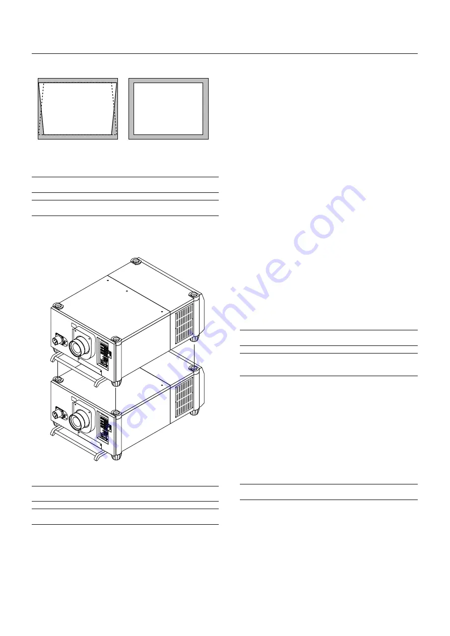
Keystone
Keystone distortion
Normal
Keystone is the distortion of a projected image that usually creates a
wider top than bottom. Aiming a projector upward on a wall rather than
straight at a wall creates this distortion. Use the
䊴
or
䊳
buttons on the
slide bar to correct this keystone (trapezoidal) distortion.
NOTE:
The keystone feature is not available when the test pattern or the blue
background is displayed.
NOTE:
With the projector aimed directly at the screen the maximum keystone
angle that can be corrected is +/- 7.5 degrees.
Setting up for Double Stacking in Link Mode
CAUTION:
To prevent the projectors from falling, install them in a place and
fasten them in a way with sufficient strength to support the two projectors.
NOTE:
SW 1 Level and SW 2 Level of Switcher Control are not available in Link
Mode.
1) Stacking the Projectors
1-1. Place the projectors at the proper height for best screen to projec-
tor relationship. Make sure that all projectors have the same display
orientation.
2) Hookup
2-1. Use the supplied DVI-D cable to connect the RGB DIGITAL output
of the master projector to the RGB DIGITAL input (INPUT9 ) of the
slave projector until all the projectors are connected.
2-2. Next, using a commercially available, bi-directional RS-232C cable
connect the OPTION OUT terminal of the master projector to the
OPTION IN terminal of the slave projector until all the projectors are
connected.
2-3. Turn all the projectors on and roughly make some optical adjust-
ments to each projector.
3) Adjusting and registering signals to be projected in Link mode
and stack application.
Signal Data Preparation
3-1. Create data for the master projector and copy data to the slave
projector.
3-1-1. Choose one projector as the master.
3-1-2. Turn the master projector on.
3-1-3. Display all desired input signals, make adjustment to each
signal, then save all adjustments on the master projector. (Ad-
justments will be saved automatically.)
3-1-4. Turn the master projector off (standby mode).
3-1-5. Store all the adjustments on a PC card from the master pro-
jector.
3-1-5-1. Open the PC Card slot cover to access the PC card slot.
Insert a PC card into this slot.
NOTE:
DO NOT TURN OFF THE POWER while the PC Card Access indicator
is flashing. Doing so will cause damage to the data of the projector system.
NOTE:
Back up your data if you use the supplied CompactFlash card to copy
the data from the master projector to the slave projector. The supplied
CompactFlash card contains data and firmware for factory use.
3-1-5-2. Press and hold CANCEL, then press POWER on the
rear panel of the master projector. The POWER indicator will
change to steady green and the PC Card Access indicator
will start flashing. After storing data on the PC card, the
POWER indicator will change to orange.
3-1-5-3. Remove the PC card from the slot of the master projec-
tor.
3-1-6. Transfer the data to the slave projector using the PC card so
that all the projectors have the same data in memory.
3-1-6-1. Insert the PC card into the slot of a slave projector.
NOTE: Since data in the slave projector will be lost at this time, make backup
copies of them before proceeding.
3-1-6-2. Press and hold ENTER, then press MENU on the rear
panel of the slave projector. The POWER indicator will change
to steady green and the PC Card Access indicator will start
flashing to indicate that the data is being copied from the PC
card to the slave projector. After copying data to the slave
projector, the POWER indicator will change to orange.


