background image

CHAPTER 2

ND-70684 (E)

Page 16
Revision 1.0

INSTALLATION PROCEDURE
Connection Diagram for the Add-On Module

2. Connection Diagram for the Add-On Module

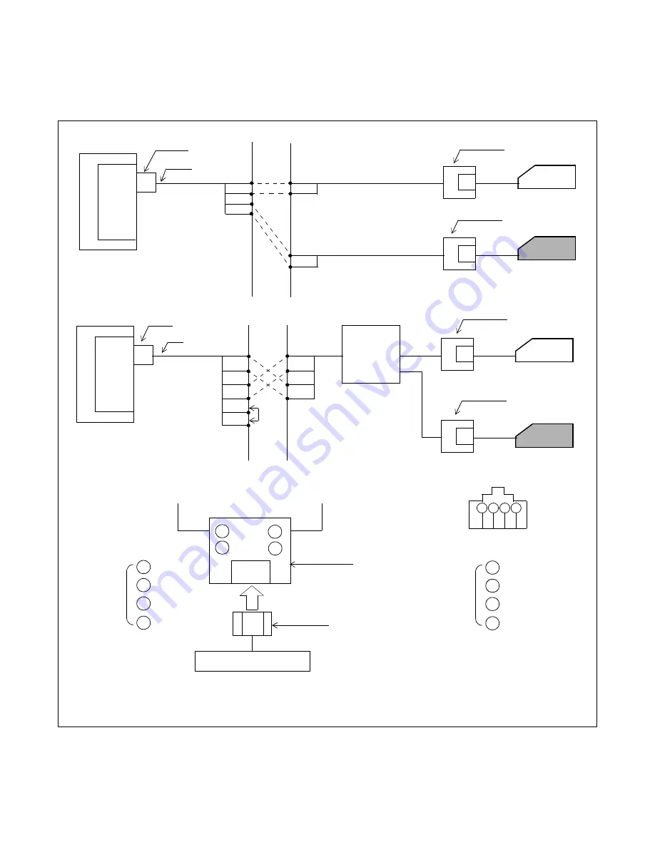
When the DSS console is used as an Add-On Module, connect the associated cables referring to 

Figure 2-2

.

Figure 2-2   Connection Diagram for the Add-On Module

Note 1:

For more detailed information on the DAU, see the NEAX2400 IMX DAU System Manual.

Note 2:

These leads are not used for this system.

PIM

ELC

Connection Diagram

PIM

MDF

TA

TB

RA

RB

RA

TB

TA

RB

Pout A

Pout B

Distributed

Access

Unit

(DAU)

Note 1

Note 2

Modular Rosette

DAI

LT Connector

Installation

Cable

1

2

3

4

1

2

3

4

A0

B0

(Polarity can be reversed.)

- Red

-Green

-Black

-Blue

DSS Console

1 2 3 4

1

2

3

4

- Yellow

-Green

-Red

-Black

4-Core Modular Jack

(As viewed from inserting direction.)

Modular Plug

Modular Rosette

Connection for Modular Rosette

A0
B0
A1
B1

A0
B0

A1

B1

LT Connector

Installation

Cable

MDF

D

term

Add-On Module

D

term

Modular Rosette

Modular Rosette

Add-On Module

Modular Rosette

Summary of Contents for NEAX 2400 IMX

Page 1: ...AUGUST 1999 NECAmerica Inc ND 70684 E ISSUE 1 STOCK 200863 Direct Station Selection DSS Console System Manual...

Page 2: ...America Inc has prepared this document for use by its employees and customers The information contained herein is the property of NEC America Inc and shall not be reproduced without prior written appr...

Page 3: ...General Service Conditions 6 6 DSS BLF 7 7 Add On Module 10 CHAPTER 2 INSTALLATION PROCEDURE 15 1 Connection Diagram for DSS BLF 15 2 Connection Diagram for the Add On Module 16 3 Cable Lead Location...

Page 4: ...TABLE OF CONTENTS ND 70684 E Page ii Revision 1 0 This page is for your notes...

Page 5: ...or DSS BLF Mode 8 Figure 1 7 DSS Key Allocation DSS BLF 9 Figure 1 8 Example of Port Designation for Add On Module 11 Figure 1 9 Line Feature Access Key Allocation Add ON Module 12 Figure 2 1 Connecti...

Page 6: ...LIST OF FIGURES ND 70684 E Page iv Revision 1 0...

Page 7: ...e 1 1 Relationship between the Mode Designation and the Mounting Level Numbers 4 Table 1 2 System Specifications for DSS 5 Table 1 3 Cable Distance Limitations 5 Table 1 4 Level Assignment Conditions...

Page 8: ...LIST OF TABLES ND 70684 E Page vi Revision 1 0 This page is for your notes...

Page 9: ...the NEAX2400 IMX Installation Manual for the PBX system to which the DSS console is connected When the DSS console is located in a Distributed Access Unit DAU the NEAX2400 IMX Installation Manual for...

Page 10: ...er explains how to install a DSS console and contains cabling diagrams showing how to connect the console to a PBX CHAPTER 3 OFFICE DATA ASSIGNMENT This chapter explains how to program the Office Data...

Page 11: ...placed on hold This function is called the Direct Station Selection DSS Each key on the console has a Light Emitting Diode LED to indicate the Busy Idle status of each assigned station so the DSS can...

Page 12: ...ionship between the Mode Designation and the Mounting Level Numbers MODE ALLOWABLE LEVEL NUMBERS DSS mode Even Number LV0 LV2 LV4 LV6 ADM mode Odd Number LV1 LV3 LV5 LV7 In this Add Mode each key can...

Page 13: ...Power Source AC 100 Volt 10 0 1A Allowable Cable Length Note See Table 1 3 for maximum cable dis tance information 850 m 2800 feet AC adapter is required Interface Card for the PBX PA 16ELCJ PA DAIG A...

Page 14: ...tation Wire 0 4 mm 051 in 26 AWG 0 5 mm 019 in 24 AWG REAR VIEW ADM Dterm Dterm Dterm ADM Dterm DSS BLF ELC LV 7 6 5 4 3 2 1 0 ADM Dterm Dterm Dterm ADM Dterm DSS BLF No terminal can be wired to this...

Page 15: ...es 2 consecutive ports on an ELC DAI card When a DSS console is used as a DSS BLF be sure to assign and wire the DSS BLF to a specific LEN whose level LV is an even number LV 0 2 4 6 Since a DSS BLF r...

Page 16: ...LV 7 6 5 4 3 2 1 0 ELC 00 05 04 03 02 01 54 59 58 57 56 55 48 53 52 51 50 49 42 47 46 45 44 43 36 41 40 39 38 37 30 35 34 33 32 31 24 29 28 27 26 25 18 23 22 21 20 19 12 17 16 15 14 13 06 11 10 09 08...

Page 17: ...4 13 06 11 10 09 08 07 DSS BLF LV0 KYN of AKYD 40 39 38 37 36 35 34 17 16 15 14 13 12 11 10 9 8 7 6 5 4 3 2 1 Dterm LV1 KYN of AKYD 40 39 38 37 36 35 34 17 16 15 14 13 12 11 10 9 8 7 6 5 4 3 2 1 Among...

Page 18: ...s usual when this feature has been set to the terminal 7 Add On Module A maximum of 48 lines and 12 feature keys may be programmed for an Add On Module One Add On Module occupies only one port on an E...

Page 19: ...tion for Add On Module 00 05 04 03 02 01 54 59 58 57 56 55 48 53 52 51 50 49 42 47 46 45 44 43 36 41 40 39 38 37 30 35 34 33 32 31 24 29 28 27 26 25 18 23 22 21 20 19 12 17 16 15 14 13 06 11 10 09 08...

Page 20: ...5 34 33 32 31 24 29 28 27 26 25 18 23 22 21 20 19 12 17 16 15 14 13 06 11 10 09 08 07 Dterm LV0 KYN of AKYD 39 38 37 36 35 34 24 23 33 21 20 19 18 17 16 15 14 Add On Module LV1 KYN of AKYD 39 38 37 36...

Page 21: ...EMINDER FKY 6 My Line and or Prime Line of the master Dterm KYNs 49 through 60 cannot be assigned for line features I USE INDICATION I HOLD INDICATION can not be used since these keys are not equipped...

Page 22: ...CHAPTER 1 ND 70684 E Page 14 Revision 1 0 This page is for your notes...

Page 23: ...ore detailed information on the DAU see the NEAX2400 IMX DAU System Manual Note 2 These leads are not used for this system PIM PIM MDF MDF A0 A0 B0 B0 TA TB RA RB RA TB TA RB Pout A Pout B Distributed...

Page 24: ...e 2 These leads are not used for this system PIM ELC Connection Diagram PIM MDF TA TB RA RB RA TB TA RB Pout A Pout B Distributed Access Unit DAU Note 1 Note 2 Modular Rosette DAI LT Connector Install...

Page 25: ...Sys tem Manual Figure 2 3 Example of Cable Lead Location 26 27 28 29 30 31 32 33 34 35 36 37 38 39 40 41 42 43 44 45 46 47 48 49 50 1 2 3 4 5 6 7 8 9 10 11 12 13 14 15 16 17 18 19 20 21 22 23 24 25 B...

Page 26: ...CHAPTER 2 ND 70684 E Page 18 Revision 1 0 This page is for your notes...

Page 27: ...signed as follows Figure 3 1 Example of Data Programming for DSS BLF TERMINAL LINE EQUIPMENT NUMBER LEN STATION NUMBER STN DSS BLF 000100 200 201 Note Dterm 000107 400 2n 1 2n LV 7 6 5 4 3 2 1 0 ELC N...

Page 28: ...irst port LV 0 in this example and the remaining lower DSS keys KYNs 31 60 are assigned using the second port LV 1 in this example Either KYN 1 or KYN 2 can be assigned first Be sure to assign the ass...

Page 29: ...numbers to the corresponding DSS keys on the console In this instance KYNs 10 39 are used The upper and lower 30 keys are associated with even numbered ports and odd num bered ports as shown below KY...

Page 30: ...57 56 55 48 53 52 51 50 49 42 47 46 45 44 43 36 41 40 39 38 37 30 35 34 33 32 31 24 29 28 27 26 25 18 23 22 21 20 19 12 17 16 15 14 13 06 11 10 09 08 07 Use KYNs 10 39 of an even numbered LEN level 0...

Page 31: ...0 Even numbered LEN level 1 Odd numbered LEN level TENANT NUMBER TN 1 63 STATION NUMBER STN Max 5 Digits LINE EQUIPMENT NUMBER LENS TELEPHONE EQUIPMENT CLASS TEC 1 31 ROUTE RESTRICTION CLASS RSC 0 15...

Page 32: ...PL TN STATION NUMBER PL ST 0 X 400 Dterm 0 X 0 0 _ _ 1 KEY NUMBER KYN 1 16 SERVICE CONDITION KY 0 2 FEATURE KEY CODE FKY 1 320 KIND OF LINE KD 0 2 MULTI LINE INTERCOM TENANT NUMBER TN 1 15 STATION NUM...

Page 33: ...ST 0 X 400 Dterm 0 X 0 0 _ _ 1 KEY NUMBER KYN 1 16 SERVICE CONDITION KY 0 2 FEATURE KEY CODE FKY 1 320 KIND OF LINE KD 0 2 MULTI LINE INTERCOM TENANT NUMBER TN STATION NUMBER STN RING INFORMATION FOR...

Page 34: ...L TN STATION NUMBER PL STN 0 X 400 Dterm 0 X 0 0 1 KEY NUMBER KYN 1 16 SERVICE CONDITION KY 0 2 FEATURE KEY CODE FKY 1 320 KIND OF LINE KD 0 2 MULTI LINE INTERCOM TENANT NUMBER TN STATION NUMBER STN R...

Page 35: ...L ST 0 X 400 Dterm 0 X 0 0 1 KEY NUMBER KYN 1 16 SERVICE CONDITION KY 0 2 FEATURE KEY CODE FKY 1 320 KIND OF LINE KD 0 2 MULTI LINE INTERCOM TENANT NUMBER TN STATION NUMBER STN RING INFORMATION FOR EA...

Page 36: ...NUMBER LEN STATION NUMBER ST Add On Module 000101 201 Note Dterm 000100 200 2n 1 2n LV 7 6 5 4 3 2 1 0 ELC Note Station number 201 is only used to assign Line Feature access keys for the Add On Module...

Page 37: ...LV 1 is used STEP 2 AKYD Assign Line Feature access keys to the Add On Module The upper 24 Line Feature access keys be long to the associated Dterm and the remaining lower 36 Line Feature access keys...

Page 38: ...to assign key information for the last 36 keys on the ADM TN X STN 201 TP 1 Buttons 1 39 are assignable PRI 0 PL TN X PL STN 200 Enter the associated Dterm as a PL STN S 0 Off Hook Suppression is off...

Page 39: ...7 56 55 48 53 52 51 50 49 42 47 46 45 44 43 36 41 40 39 38 37 30 35 34 33 32 31 24 29 28 27 26 25 18 23 22 21 20 19 12 17 16 15 14 13 06 11 10 09 08 07 Use KYNs 5 40 of the Add On Module for programmi...

Page 40: ...ER TN STATION NUMBER STN X 200 Dterm PRIORITY FOR ANSWERING CALL PRI PRIME LINE ALLOW OG FROM PRIME LINE S 0 1 MESSAGE WAITING DATA DISPLAY SELECTION MWD 0 1 LINE PREFERENCE LN PRE 0 1 LINE PREFERENCE...

Page 41: ...term 0 X 0 0 1 KEY NUMBER KYN SERVICE CONDITION KY 0 2 FEATURE KEY CODE FKY 1 320 KIND OF LINE KD 0 2 MULTI LINE INTERCOM TENANT NUMBER TN STATION NUMBER STN RING INFORMATION FOR EACH LINE RG 0 7 KIND...

Page 42: ...ELECTION MWD 0 1 LINE PREFERENCE LN PRE LINE PREFERENCE FOR SPEAKER BUTTON SPK 0 3 LINE PREFERENCE FOR ANSWER BUTTON ANS 0 2 LINE PREFERENCE FOR OUTGOING BUTTON ORG 0 1 TYPE OF Dterm TENANT NUMBER PL...

Page 43: ...TENANT NUMBER PL TN STATION NUMBER PL STN 0 X 201 Add On Module 0 X 0 0 1 KEY NUMBER KYN SERVICE CONDITION KY 0 2 FEATURE KEY CODE FKY 1 320 KIND OF LINE KD 0 2 MULTI LINE INTERCOM TENANT NUMBER TN S...

Page 44: ...TYPE OF Dterm TENANT NUMBER PL TN STATION NUMBER PL STN 0 X 201 Add On Module 0 X 0 0 1 KEY NUMBER KYN SERVICE CONDITION KY 0 2 FEATURE KEY CODE FKY 1 320 KIND OF LINE KD 0 2 MULTI LINE INTERCOM TENA...

Page 45: ...ata setting sheets for commands used by DSS You can use these sheets to plan your data before installing the DSS 5 1 ASDT TENANT NUMBER TN 1 63 STATION NUMBER STN 5 DIGITS LINE EQUIPMENT NUMBER LENS T...

Page 46: ...LINE PREFERENCE FOR SPEAKER BUTTON SPK 0 3 LINE PREFERENCE FOR ANSWER BUTTON ANS 0 2 LINE PREFERENCE FOR OUTGOING BUTTON ORG 0 1 TYPE OF Dterm TP 0 3 TENANT NUMBER PL TN STATION NUMBER PL STN KEY NUMB...

Page 47: ...ata for FKY only Note 3 When KYI Multi Line assign data for multiple telephone only KEY NUMBER KYN SERVICE CONDITION KYI 0 2 FEATURE KEY CODE FKY 1 320 KIND OF LINE KD 0 2 MULTI LINE INTERCOM TENANT N...

Page 48: ...PREFERENCE FOR SPEAKER BUTTON SPK 0 3 LINE PREFERENCE FOR ANSWER BUTTON ANS 0 2 LINE PREFERENCE FOR OUTGOING BUTTON ORG 0 1 TYPE OF Dterm TP 0 3 TENANT NUMBER PL TN STATION NUMBER PL STN KEY NUMBER K...

Page 49: ...ata for FKY only Note 3 When KYI Multi Line assign data for multiple telephone only KEY NUMBER KYN SERVICE CONDITION KYI 0 2 FEATURE KEY CODE FKY 1 320 KIND OF LINE KD 0 2 MULTI LINE INTERCOM TENANT N...

Page 50: ...CHAPTER 3 ND 70684 E Page 42 Revision 1 0 This page is for your notes...

Reviews: