background image

1. Installing Internal Optional Devices 


Express5800/R120d-1M  User’s Guide 

56 

Chapter 2  Preparations 

Note 

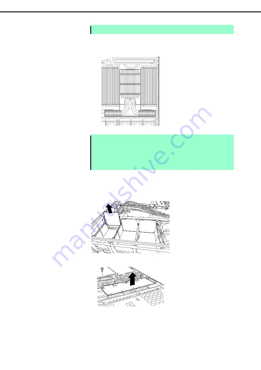
Make sure the location to put the heat sink. 


13.  Make sure that the heat sink is installed on a level with the motherboard. 


Note 

  If the heat sink is not level, remove it, and then install it again.   

The following probably causes the heat sink not to be level: 
– The CPU is not positioned correctly. 
– All screws are not completely tightened. 

  Do not move the secured heat sink.


14.  Install an additional fan unit provided with additional CPU board. Remove fan cover from the slot 

where you are going to install an additional fan. 


15.  Remove a single screw from the tray, and remove the battery tray for RAID Controller. 


REAR 

FRONT 

Summary of Contents for N8100-1794F

Page 1: ...800 Series 10 021 01 101 01 April 2012 First Edition NEC Corporation 2012 Express5800 R120d 1M EXP291 User s Guide Model Number N8100 1794F Chapter 1 General Description Chapter 2 Preparations Chapter...

Page 2: ...ons connection of peripheral devices and ideal location for this server Chapter 3 Setting Up Your Server System BIOS configurations and summary of EXPRESSBUILDER Chapter 4 Appendix Specifications and...

Page 3: ...r supply and power cord use 15 Installation relocation storage and connection 16 Cleaning and working with internal devices 17 During operation 18 Warning labels 19 External view 19 Handling precautio...

Page 4: ...sing Memory RAS Feature 65 1 11 Battery for RAID Controller 73 1 11 1 Handling precautions 73 1 11 2 Installing Battery N8103 153 162 73 1 11 3 Removal 75 1 12 LAN Riser Card 76 1 12 1 Installation 76...

Page 5: ...error messages 115 2 BIOS Setup Utility SETUP 116 2 1 Overview 116 2 2 Starting and Exiting SETUP Utility 116 2 2 1 Starting SETUP 116 2 2 2 Exiting SETUP 116 2 3 Description on On Screen Items and K...

Page 6: ...e Indicates items that must be confirmed when handling the server or operating software Tips Indicates information that is helpful to keep in mind when using this server Optical disk drives This serve...

Page 7: ...ows Server 2003 R2 Standard Windows Server 2003 R2 Enterprise Windows Server 2003 2 Windows Server 2003 Standard Windows Server 2003 Enterprise Windows 7 Windows 7 Professional 64 bit x64 Edition Wind...

Page 8: ...or trademarks of Adaptec Inc of the United States LSI and the LSI logo design are trademarks or registered trademarks of LSI Corporation Adobe the Adobe logo and Acrobat are trademarks of Adobe System...

Page 9: ...que de la classe A est conforme la norme NMB 003 du Canada CE Australia and New Zealand Statement This is a Class A product In domestic environment this product may cause radio interference in which c...

Page 10: ...omissions please contact your retailer 5 Regardless of these 4 items NEC Corporation does not take responsibility for effects resulting from operations 6 The sample values used in this document are n...

Page 11: ...WARNING or CAUTION is used to indicate a degree of danger These terms are defined as follows WARNING Indicates there is a risk of death or serious personal injury CAUTION Indicates there is a risk of...

Page 12: ...shock or fire may be caused Do not touch the server with wet hand Otherwise an electric shock may be caused Do not touch the component specified by this symbol Otherwise an electric shock or burn may...

Page 13: ...shock Use a rack that conforms to the designated standard This server can be mounted onto a 19 inch rack that conforms to EIA standards Do not mount the server onto any rack that does not conform to E...

Page 14: ...ponents such as the door or rails When installing the door make sure that both upper and lower hinge pins are held in place Incomplete attachment may cause components to fall off as well as personal i...

Page 15: ...ngle outlet by using extension cords The electric current exceeding the rated flow overheats the outlet which may cause a fire Insert the power plug into the outlet as far as it goes Heat generation r...

Page 16: ...ied Do not install the server in the following places or any place other than specified in this User s Guide Failure to follow this instruction may cause a fire A dusty place A humid place such as nea...

Page 17: ...the server with loose cable connections Do not use any damaged cable Cleaning and working with internal devices WARNING Do not disassemble repair or alter the server Never attempt to disassemble repa...

Page 18: ...rver during thunderstorms Do not touch any part of the server including the cables when a thunderstorm is approaching Also do not connect or disconnect any devices There may be a risk of electric shoc...

Page 19: ...tial hazards This label is either attached or printed on the component to draw attention from users to potential hazards involved in handling the server Do not remove or black out this label and keep...

Page 20: ...d We do not guarantee that any copy protected CD that does not conform to standards will play on the server s optical disk drive In the following cases check and adjust the system clock before operati...

Page 21: ...from reflecting bright lights and to make the display contents easy to see Working without adjusting the display to a comfortable angle makes it difficult for you to maintain a proper posture and you...

Page 22: ...e features of this server and the name of each part 1 Introduction 2 Accessories Verify the condition of your server s accessories 3 Standard Features This section describes the server s features and...

Page 23: ...processor NEC s latest technology and architectures realize high power and high speed operation that cannot be matched by existing servers The server is designed with consideration of not only reliabi...

Page 24: ...tting Started 1 Documents are stored in EXPRESSBUILDER Adobe Reader is required to read the documents so make sure you have it installed in your PC Make sure you have all accessories and inspect them...

Page 25: ...s supported High reliability Processor throttle ring feature Memory monitoring feature error correction error detection Memory degeneracy feature logical isolation of a failed device Memory x4 SDDC fe...

Page 26: ...processor system with up to two processors Expansion Bay for hard disk drives 8 slots 4 Optical disk drive bay provided as standard 5 USB2 0 interface Front 2 ports rear 4 ports internal 2 ports Three...

Page 27: ...ng EXPRESSSCOPE Profile Key 1 Unsupported on Xeon processor E5 2609 embedded models 2 Processor core speed depends on processor type number and type of DIMMs installed and operating voltage 1 35 1 5 V...

Page 28: ...ial ports keyboard mouse and video System environment Monitors temperatures fans voltage power supply and others Temperature Monitors the temperature inside of the chassis Fan Monitors the fans Voltag...

Page 29: ...Version Management Use of NEC ESMPRO Manager and ExpressUpdate Agent allows you to manage versions of firmware and software as well as update them by applying update packages This feature automatical...

Page 30: ...his LED turns on when the server is connected to the network See page 39 3 1 LAN connector 1 3 2 LAN connector 2 3 3 LAN connector 3 3 4 LAN connector 4 LEDs for LAN3 and LAN4 are lit when optional LA...

Page 31: ...s this switch to reset the server 14 DUMP Switch NMI When DUMP Switch is pressed memory dump is performed 15 Unit ID UID Switch LED The switch to turn on and off UID LED Pressing the switch once turns...

Page 32: ...y LAN connector 1 can also be used as the management LAN port However sharing port is not recommended from the point of performance and security because LAN port 1 may receive both data 11 SPEED LED T...

Page 33: ...4 Names and Functions of Parts Express5800 R120d 1M User s Guide 33 Chapter 1 General Description 4 4 External View 1 Top Cover 2 Release Button...

Page 34: ...N5F R 6 FAN6F R optional 7 FAN7F R optional 8 FAN8F R optional FAN1 to FAN5 are factory installed FAN6 to FAN8 are required in 2 CPU configuration 4 Processor Optional 5 DIMM optional 6 Support bar 7...

Page 35: ...and Functions of Parts Express5800 R120d 1M User s Guide 35 Chapter 1 General Description 4 6 Motherboard 5 22 8 1 27 25 5 13 17 16 14 15 14 12 11 10 9 26 8 2 7 6 5 4 3 2 1 1 2 1 2 2 5 18 5 23 19 13 2...

Page 36: ...n additional RS 232C connector kit N8117 01A to use this port as a serial port 17 SPI Flash Mezzanine connector EXPRESSSCOPE Profile Key SPI flash memory has been installed where BIOS and BMC configur...

Page 37: ...status of the server The following table lists POWER LED patterns and their explanation POWER LED pattern Explanation On green The server is normally powered on On amber BMC is being initialized When...

Page 38: ...DUMP Switch is pressed Note It remains green if the dump is caused by software Wait until the memory dump is completed On amber A temperature alarm was detected Check the internal fan for dusts Also...

Page 39: ...t your sales representative Flashing green and amber alternately only when RAID system is configured Rebuild is in progress Off Hard disk drive is halted 4 7 5 Optical Disk Drive Access LED The LED fo...

Page 40: ...Contact your sales representative Flashing green and amber alternately only when RAID system is configured Rebuild is in progress When the failed hard disk drive is replaced rebuild process starts aut...

Page 41: ...server is accessing network Off The server is disconnected from network SPEED LED 1 2 M This LED indicates which network interface is used Two onboard LANs 1 2 support 1000BASE T 100BASE TX and 10BAS...

Page 42: ...ir explanation AC POWER LED pattern Explanation Solution On green The server is powered on Flashing green The power cable is connected and AC power is supplied Cold Redundant feature is enabled See pa...

Page 43: ...This chapter describes preparations for using this server 1 Installing Internal Optional Devices You can skip this section if you did not purchase any optional devices 2 Location and Connection You mu...

Page 44: ...and remove optional devices properly and safely WARNING Be sure to observe the following precautions to use the server safety Failure to observe the precautions may cause death or serious injury For...

Page 45: ...y periodically touching a metal surface while working on the components Select a suitable work space Work with the server on the anti static or concrete floor If you work with the server on a carpet w...

Page 46: ...omponents 1 If the server is mounted on a rack use the UID switch to identify the target server Refer to Chapter 2 1 4 Confirming Servers UID Switch 2 Remove Front Bezel Refer to Chapter 2 1 5 Removin...

Page 47: ...Attach Top Cover Refer to Chapter 2 1 17 Installing Top Cover 9 Mount the server onto the rack Refer to Chapter 2 2 1 2 1 Installation 10 Install hard disk drives Refer to Chapter 2 1 18 Hard Disk Dri...

Page 48: ...ID Unit ID Switch helps you to identify the target server When the server is working before you turn the server off or disconnect a cable from the server be sure to identify the target server by using...

Page 49: ...Bezel follow the steps below 1 Insert the attached Bezel Lock Key into the key slot and turn the key to the front bezel side while pressing it lightly to release the lock 2 Pull the Front Bezel toward...

Page 50: ...drive LAN riser card DIMM Processor TPM module Internal Flash Memory Additional HDD cage PCI card RAID Controller Battery for RAID Controller 1 Refer to steps 1 to 5 in Chapter 2 1 3 Overview of Insta...

Page 51: ...Memory optional 1 7 1 Installation Install Internal Flash Memory in the following procedure 1 Refer to steps 1 to 6 in Chapter 2 1 3 Overview of Installation and Removal for preparations 2 Attach Inte...

Page 52: ...re for installing optional TPM Kit 1 8 1 Installation Install TPM Kit in the following procedure 1 Refer to steps 1 to 6 in Chapter 2 1 3 Overview of Installation and Removal for preparations 2 Instal...

Page 53: ...e of the processor as well as the motherboard Repair of the server due to failures or damage resulted from installing such a processor will be charged Tips After adding the processor Windows may recor...

Page 54: ...om the hook then slowly open the lever until it stops 6 Push down the socket lever marked with once to unlatch it from the hook then slowly open the lever until it stops 7 Lift the plate Important Do...

Page 55: ...on the CPU socket Bring down the processor straight without tilting or sliding it in the socket 9 Lightly push the processor to the CPU socket and close the plate 10 Close the socket lever marked with...

Page 56: ...vel remove it and then install it again The following probably causes the heat sink not to be level The CPU is not positioned correctly All screws are not completely tightened Do not move the secured...

Page 57: ...n it on 20 Run BIOS Setup Utility SETUP to confirm the following settings Refer to Chapter 2 1 Details of System BIOS in Maintenance Guide Advanced Processor Configuration Processor Information CPU ID...

Page 58: ...M is factory installed in standard configuration 1 10 1 Maximum supported memory size The maximum available memory size on the server depends on the architecture and OS specs List of maximum memory si...

Page 59: ...Memory Kit N8102 476 6GB DDR3 1600 REG Memory Kit N8102 477 12GB DDR3 1600 REG Memory Kit N8102 499 24GB DDR3 1600 REG Memory Kit N8102 500 48GB DDR3 1600 REG Memory Kit DIMMs installed on N8101 546F...

Page 60: ...3 1600 REG Memory Kit 1333 MHz 1066 MHz 1600 MHz 1066 MHz N8102 469F 8GB DDR3 1600 REG Memory Kit N8102 470F 16GB DDR3 1600 REG Memory Kit N8102 471F 32GB DDR3 1600 REG Memory Kit N8102 440F 64GB DDR3...

Page 61: ...l memory board See the table below for RAS features supported by additiional memory board List of features supported by additiional memory board N code Product name Standard feature x4 SDDC Memory Mir...

Page 62: ...the table below to find allowable combination of DIMMs and install DIMMs starting from the largest capacity and from the smallest slot number N code N8102 435F 468F 469F 470F 471F 440F 472 473 474 475...

Page 63: ...rt 4 Attach the duct 5 Continue to install or remove internal optional devices mount and connect the server and turn it on 6 Confirm that no error messages are displayed in POST screen If any error me...

Page 64: ...e DIMM is installed At least one DIMM needs to be installed for the server to operate Take the steps below after replacing or removing DIMMs 1 Confirm that no error messages are displayed on POST If a...

Page 65: ...omatic correction of memory error multi bit error Note Refer to List of features supported by additiional memory board in 1 10 3 Memory RAS Feature before using memory RAS feature Only the features th...

Page 66: ...nnels 0 and 1 or channels 2 and 3 To use Memory Mirroring feature install N8102 472 473 474 475 additional memory board two DIMMs of same model DIMMs to be installed in mirror set must have same capac...

Page 67: ...owing parameter Advanced Memory Configuration Memory Information CPUx_DIMMx Status Installation order depends on CPU configuration See the figure below Memory Mirroring cannot be configured in the fol...

Page 68: ...tion With this feature a single device can detect and correct one to eight bit error Note Memory LockStep feature uses channels 0 and 1 or channels 2 and 3 To use Memory LockStep feature install N8102...

Page 69: ...e below Memory Lock Step cannot be configured in the following cases Memory Lock Step between memory channels of different memory controllers CPU Memory Lock Step within the same memory channel Notes...

Page 70: ...ng feature install N8102 476 477 499 500 additional memory board three DIMMs of same model Tips The operating system recognizes the DIMMs as those with capacities less than the actual physical capacit...

Page 71: ...splayed in Sparing Refer to Chapter 2 1 System BIOS in Maintenance Guide run SETUP change parameters as shown below save the settings and exit from SETUP Advanced Memory Configuration Memory RAS Mode...

Page 72: ...u additionally install DIMMs that unable to configure Memory Sparing When you remove DIMMs that takes down Memory Sparing 1CPU 2CPU 3 3 3 4 4 4 2 2 2 1 1 1 5 5 5 7 7 7 3 3 3 1 1 1 6 6 6 8 8 8 4 4 4 2...

Page 73: ...roperty such as data or other devices might be destroyed Use the battery that supports the RAID Controller used The battery is a very delicate electronic device Before installation touch the metal fra...

Page 74: ...RAID Controller See the figure on the right Install N8103 162 additional battery to the position for PCI slot 1 or 1C PCI 1B 1C RAID PCI 1A RAID 7 Install the battery tray for RAID Controller using a...

Page 75: ...ews you have removed in Step 8 12 Install RAID Controller to the RAID Controller connector on motherboard using two screws you have removed in Step 10 13 Connect Mini SAS cable to RAID Controller 14 I...

Page 76: ...AN Riser Card Important You must avoid static electricity to work with the procedure below For details refer to Chapter 2 1 2 Anti static Measures 1 12 1 Installation Follow steps below to install LAN...

Page 77: ...h the LAN Riser Card slot and insert the card securely 7 Secure the bracket of LAN Riser Card with two screws you have removed in step 5 8 Install the port cover provided with LAN Riser Card 1 12 2 Re...

Page 78: ...card slot Slot 1D dedicated to LAN riser card The PCI devices of the same type including onboard PCI device may be recognized in different order from that described above depending on OS or RAID Conf...

Page 79: ...ist supported boards and slots available for them For details of the features of each board refer to the manual supplied with it Tips Different boards mounted on the same bus operate at the lower freq...

Page 80: ...04 135 1000BASE T Riser Card 2ch PCI EXPRESS 2 0 x8 For additional LAN port Teaming AFT SFT ALB and bonding with onboard LAN and N8104 135 138 132 133 is supported N8104 138 1000BASE T Adapter 1ch PCI...

Page 81: ...ation position with the reference to the table on 1 14 2 Supported boards and available slots 4 Remove the screw from the PCI riser card and remove the blank cover Note Keep the removed blank cover fo...

Page 82: ...Error Message in Maintenance Guide 10 Start the configuration utility installed on the mounted board to set up the board Availability or startup and operation procedure of the utility depends on board...

Page 83: ...ty select PCI Configuration from the Advanced menu and then make sure that the parameter of PCI Slot xx ROM xx is PCI slot number is set to Enabled When connecting a RAID Controller set the boot prior...

Page 84: ...RAID Controller 9 2 When five or more hard disk drives are installed Connect SAS SATA cable removed in Step 9 to connector Ports 0 3 on RAID Controller Connect SAS SATA cable provided with the server...

Page 85: ...usively with the optical disk drive 1 14 1 Installation Follow steps below to install an additional HDD cage 1 Refer to steps 1 to 6 in Chapter 2 1 3 Overview of Installation and Removal for preparati...

Page 86: ...additional HDD cage to the chassis and secure it with screws 1 14 2 Removal To remove additional HDD cage reverse the installation procedure Important Before removing additional HDD cage be sure to r...

Page 87: ...sk drive 1 15 1 Installation Install an optical disk drive in the following procedure 1 Refer to steps 1 to 6 in Chapter 2 1 3 Overview of Installation and Removal for preparations 2 Remove the two sc...

Page 88: ...tray 6 Secure the bracket to optical disk drive with a screw you have removed in Step 3 7 Insert the optical disk drive and secure the drive tray with two screws you have removed in Step 2 8 Connect t...

Page 89: ...contains valuable data be sure to backup the hard disk drive before installing the RAID Controller and configuring the RAID System Note In the RAID System use hard disk drives that have the same spec...

Page 90: ...RAID Controller Hard Disk Drive Backplane Ports 0 3 SLOT 0 SATA 0 SLOT 1 SATA 1 SLOT 2 SATA 2 SLOT 3 SATA 3 Ports 4 7 SLOT 4 SATA 4 SLOT 5 SATA 5 When optional 2 5 inch HDD cage is installed Optional...

Page 91: ...ives in a group pack must have the same capacity interface type and rotational speed If you intend to install the OS to the RAID System the process from RAID configuration to OS installation can be ea...

Page 92: ...7 Installing Top Cover When all internal optional devices are installed close the server with Top Cover 1 Put Top Cover straight on the server chassis so that it can be surely engaged with the chassis...

Page 93: ...he following precautions to install hard disk drives For onboard connection hard disk drives having different capacities types or rotational speeds cannot be installed together In the RAID System all...

Page 94: ...of Installation and Removal for preparations 2 Locate the slot where you install the hard disk drive The server has 6 slots or 8 slots when additional HDD cage is installed Install hard disk drives i...

Page 95: ...verse the installation procedure If you transfer or dispose of the removed hard disk drive refer to Chapter 1 1 Transfer Movement and Disposal in Maintenance Guide to erase data Important NEC assumes...

Page 96: ...eplacing a hard disk drive while the power on a failed hard disk drive During the auto rebuild DISK LED on the hard disk drive flashes green and amber alternately to indicate that the auto rebuild is...

Page 97: ...N8101 552F E5 2690 2 CPUs 800 W 1 19 1 Cold Redundant Feature The server supports the feature to optimize power efficiency as described below Cold redundant feature can run the system with optimum po...

Page 98: ...move the blank cover Note Keep the removed blank cover for future use 3 Insert the power supply unit until it is locked with clicking sound 4 Connect power cords Use the power cord that comes with the...

Page 99: ...C POWER LEDs on both power supply units blink green 5 Power on the server AC POWER LEDs go on green 6 Confirm by STATUS LED or on POST screen that there are no errors related to the power supply units...

Page 100: ...d property damage For details refer to Safety precautions in Precautions for Use Pay attention to electric hazard Important Do not remove a power supply unit operating normally Tips In the redundant p...

Page 101: ...R120d 1M User s Guide 101 Chapter 2 Preparations 1 20 Installing Front Bezel When installing Front Bezel engage catch of front bezel with that on rails After installing Front Bezel lock it with Bezel...

Page 102: ...nly in the specified environment Do not connect the ground wire to a gas pipe CAUTION Be sure to observe the following precautions to use the server safely Failure to observe the precautions may cause...

Page 103: ...orrosive gases sulfur dioxide hydrogen sulfide nitrogen dioxide chlorine ammonia ozone etc exist Place where the air or dust includes components accelerating corrosion ex sulfur sodium chloride or con...

Page 104: ...cautions to use the server safely Failure to observe the precautions may cause burns injury and property damage For details refer to Safety precautions in Precautions for Use Do not drop Do not leave...

Page 105: ...nt an outer rail marked as R to the right side of the rack and L to the left side when viewed the rack from front 2 Fit the square shaped protrusions of outer rail to the square holes of a 19 inch rac...

Page 106: ...tempt to lift the server with single person Do not drop Do not leave the server being pulled out Do not install with the cover removed Do not get your fingers caught 1 Installation Mount the server to...

Page 107: ...ock on front panel clicks 2 Removal procedure Remove the server from the rack in the following procedure Important At least two persons are required to remove the server from rack 1 Make sure that the...

Page 108: ...om part of the server slowly pull out the server Do not apply pressure on the server from top when it is being pulled out Doing so cause the server to drop 3 Removing Outer Rail Remove outer rails fro...

Page 109: ...death or serious injury For details refer to Safety precautions in Precautions for Use Do not hold the power plug with wet hands Do not connect the ground wire to a gas pipe CAUTION Be sure to observ...

Page 110: ...ce Display unit 2 Hub switching hub etc Management LAN port Ports for data transmission Device with serial interface USB device FRONT REAR Finally connect the provided power cord to an outlet 1 For co...

Page 111: ...ptible Power Supply UPS To connect the power cord of the server to a UPS use the connector output on the rear of the UPS For details refer to the manual supplied with the UPS When the power cord is co...

Page 112: ...S settings by following the instructions in this section 3 EXPRESSSCOPE Engine 3 EXPRESSSCOPE Engine 3 provides useful features through Baseboard Management Controller BMC 4 EXPRESSBUILDER EXPRESSBUIL...

Page 113: ...r 1 Turn on the peripheral devices and display unit Note If the power cord is connected to power control system such as an Uninterruptible Power Supply UPS make sure that the power control system is t...

Page 114: ...If Enabled is specified for Password On Boot in Security menu of SETUP you will be prompted to enter password after the logo is displayed If you enter the incorrect password three times consecutively...

Page 115: ...troller board is installed a message that prompts you to start the dedicated utility to set each board is displayed Example If an optional RAID Controller is installed Press Ctrl H for Web BIOS The ut...

Page 116: ...g SETUP Run POST following Chapter 3 1 1 1 POST sequence After a while the following message will be displayed on the lower left of the screen Press F2 SETUP F3 Internal Flash Memory F4 ROM Utility F1...

Page 117: ...r of the selected item You cannot use this key when a menu which has on the left is selected Enter key Press this key to confirm the selected parameter Esc key Pressing this key takes you to the previ...

Page 118: ...No F3 key If you press this key the following window appears If you select Yes restore the parameters of the currently selected item to the default setting This might be different from the parameters...

Page 119: ...oller and Option ROM Settings PCIXX Slot Option ROM Disabled XX is PCI slot number of the installed option board Boot Change the boot order of devices Boot Boot Option Priorities Change the boot prior...

Page 120: ...ong password 3 times operation stops You cannot operate further Turn off the power Saving changes If you finish configuration select Save Exit and then Save Changes and Exit to save changes and exit I...

Page 121: ...lize these functions virtual USB mass storage Remote FD Remote CD DVD Remote USB Memory or Virtual Flash is always connected as USB mass storage 3 2 EXPRESSSCOPE Engine 3 Network Configuration To enab...

Page 122: ...e feature may be interrupted In this case wait for a while and connect with network again 5 If Property is selected the following screen is displayed On this screen specify Enable if you want to use D...

Page 123: ...eature select Tool menu in the menu after boot Storage of documents Stores various documents including User s Guide Installation Guide and Maintenance Guide Documents and some software components are...

Page 124: ...ftware Components Express5800 R120d 1M User s Guide 124 Chapter 3 Setup 5 Installing Software Components Continue to install software components such as OS Refer to the instructions below Installation...

Page 125: ...he server is connected to a UPS refer to the documentation supplied with the UPS or the documentation for the application controlling the UPS 1 Shut down the OS 2 The server automatically turns off af...

Page 126: ...Express5800 R120d 1M User s Guide 126 NEC Express5800 Series Express5800 R120d 1M Appendix 1 Specifications 2 Interrupt Lines 4 4...

Page 127: ...ptional port can be used up to two ports in total 2x 1000BASE T LAN connector 1000BASE T 100BASE T 10BASE T supported RJ45 2x rear 1x Management LAN connector 100BASE T 10BASE T supported RJ45 1x rear...

Page 128: ...devices Interrupt lines As factory settings interrupt lines are assigned as follows IRQ Peripheral Device Controller IRQ Peripheral Device Controller 0 System timer 12 SM Bus 1 13 Numeric data proces...

Reviews: