background image

English-13

English

1. Determine the installation location

CAUTION: 

Installing your LCD monitor must be done by a 
qualifi ed technician. Contact your dealer for more 
information.

CAUTION: 

MOVING OR INSTALLING THE LCD MONITOR 
MUST BE DONE BY TWO OR MORE PEOPLE 
FOR V552, BY FOUR OR MORE PEOPLE FOR 
V652. Failure to follow this caution may result in 
injury if the LCD monitor falls.

CAUTION: 

Do not mount or operate the monitor upside 
down, face up or face down. 

CAUTION: 

This LCD has a temperature sensor and cooling 
fans, including a fan for option board. 
If the LCD becomes too hot, the cooling fans will 
turn on automatically.
The fan of option board is active although the 
temperature is lower than normal operating 
temperature for cooling option board. If the LCD 
becomes overheated while the cooling fan is 
running, a “Caution” warning will appear. If the 
“Caution” warning appears, discontinue use and 
allow the unit to cool. Using the cooling fan will 
reduce the likelihood of early circuit failure and 
may help reduce image degradation and “Image 
Persistance”.
If the LCD is used in an enclosed area or if the 
LCD panel is covered with a protective screen, 
please check the inside temperature of the 
monitor by using the “HEAT STATUS” control 
in the OSD (see page 26). If the temperature is 
higher than the normal operating temperature, 
please turn the cooling fan to ON within the FAN 
CONTROL menu within the OSD (see page 26).

IMPORTANT: 

Lay the protective sheet, which was wrapped 
around the LCD monitor when it was 
packaged, beneath the LCD monitor so as not 
to scratch the panel.

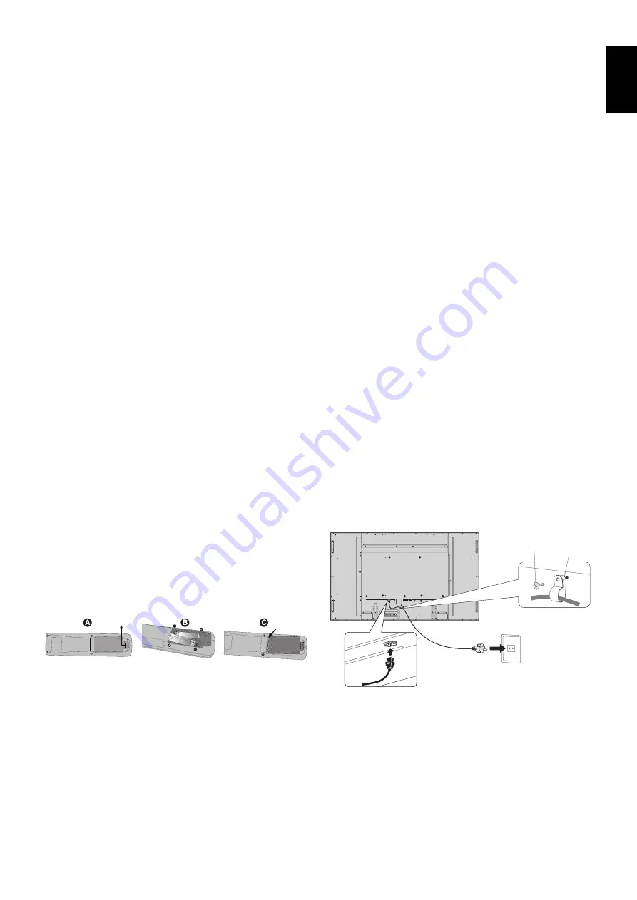
2. Install the remote control batteries

The remote control is powered by two 1.5V AA batteries. 
To install or replace batteries:

A.  Press and slide to open the cover.

B.  Align the batteries according to the (+) and (–) indications 

inside the case.

C.  Replace the cover.

CAUTION: 

 Incorrect usage of batteries can result in leaks or 

bursting. 

NEC recommends the following battery use:

• 

Place “AA” size batteries matching the (+) and (-) signs 
on each battery to the (+) and (-) signs of the battery 
compartment.

• 

Do not mix battery brands.

• 

Do not combine new and old batteries. This can shorten 
battery life or cause liquid leakage of batteries.

• 

Remove dead batteries immediately to prevent battery 
acid from leaking into the battery compartment.

• 

Do not touch exposed battery acid, it may injure skin.

NOTE: 

If you do not intend to use the Remote Control for 
a long period of time, remove the batteries.

3. Connect external equipment 
  (See pages 15 and 16)

• 

To protect the external equipment; turn off the main power 
before making connections.

• 

Refer to your equipment user manual for further 
information.

NOTE: 

Do not connect/disconnect cables when turning 
on the monitor or other external equipment as this 
may result in a loss of the monitor image.

4. Connect the supplied power cord

• 

The equipment should be installed close to an easily 
accessible power outlet.

• 

Please fasten power cord to the LCD monitor by attaching 
the screw and clamp.

• 

Fully insert the prongs into the power outlet socket. 
A loose connection may cause image degradation.

NOTE: 

Please refer to the “Safety Precautions and 
Maintenance” section of this manual for proper 
selection of AC power cord.

Clamp

Screw

Setup

Summary of Contents for MultiSync V552

Page 1: ...MultiSync V552 MultiSync V652 Please find your model name in the label on the backside of monitor Large Format Display User s Manual ...

Page 2: ...er ON and OFF Modes English 17 Power Indicator English 18 Using Power Management English 18 Selecting a video source English 18 Picture Aspect English 18 Information OSD English 19 Picture Mode English 19 OSD On Screen Display Controls English 20 PICTURE English 21 ADJUST English 21 AUDIO English 22 SCHEDULE English 22 PIP English 23 OSD English 23 MULTI DISPLAY English 24 DISPLAY PROTECTION Engli...

Page 3: ...aged to try to correct the interference by one or more of the following measures Reorient or relocate the receiving antenna Increase the separation between the equipment and receiver Connect the equipment into an outlet on a circuit different from that to which the receiver is connected Consult your dealer or an experienced radio TV technician for help If necessary the user should contact the deal...

Page 4: ...cerning the operation and maintenance of this unit has been included Therefore it should be read carefully in order to avoid any problems CAUTION CAUTION Please use the power cord provided with this monitor in accordance with the table below If a power cord is not supplied with this equipment please contact your supplier For all other cases please use a power cord that matches the AC voltage of th...

Page 5: ...ing outlet directly as it may shorten the lifetime of the monitor or cause condensation If condensation happens let the monitor stand unplugged until there is no condensation Connecting to a TV Cable distribution system should be grounded earthed in accordance with ANSI NFPA 70 the National Electrical Code NEC in particular Section 820 93 Grounding of Outer Conductive Shield of a Coaxial Cable The...

Page 6: ... DVI D cable Wireless Remote Control and AA Batteries Screw with washer M4 x 10 x 3 V552 x 1 V652 Clamp x 3 V552 x 1 V652 Thumbscrew for optional stand x 2 2 Remember to save your original box and packing material to transport or ship the monitor 1 Type and number of power cords included will depend on the where the LCD monitor is to be shipped When more than one power cord is included please use ...

Page 7: ...ded with the mounting equipment for detailed information Make sure there is no gap between the monitor and the bracket When used in a video wall configuration for a longer time slight expansion of the displays may happen due to temperature changes Due to this it is recommended that over one millimeter gap is kept between adjacent display edges Installation Orientation When using the display in the...

Page 8: ...cessive force to manipulate the optional board before fixing it with screws Figure 1 3 Installing and removing optional table top stand CAUTION Installing and removing the stand must be done by two or more people for V552 by four or more people for V652 To install follow those instructions included with the stand or mounting apparatus Use only those devices recommended by the manufacturer NOTE For...

Page 9: ...chain to the monitor using the provided clamps and screws For the V652 the clamps and screws are included with the optional table top stand V552 Screw M4 Cord or chain Clamp 295 mm Screw Holes V652 Screw M4 Cord or chain Clamp 400 mm Screw Holes included in option stand Before attaching the LCD monitor to the wall make sure that the wall can support the weight of the monitor Be sure to remove the ...

Page 10: ...en the OSD menu is turned off Acts as EXIT button within the OSD to move to previous menu 쐎 Remote control sensor and Power Indicator Receives the signal from the remote control when using the wireless remote control See also page 12 Glows green when the LCD monitor is in active mode Glows red when the LCD is in POWER OFF mode Glows amber when the monitor is in Power Save Mode Green and Amber blin...

Page 11: ...ipment 쐊VIDEO1 IN connector BNC To input a composite video signal 쐎 LAN port RJ 45 LAN connection See page 34 쐅 RS 232C D Sub 9 pin IN connector Connect RS 232C input from external equipment such as a PC in order to control RS 232C functions OUT connector Connect RS 232C output To connect multiple MultiSync monitors via RS 232C daisy Chain 쐈 REMOTE IN Black Use the optional wired remote control by...

Page 12: ... accessories are available Please contact your supplier for detailed information NOTE Please contact your supplier for available option board 씌 Internal speaker 씍 Kensington Lock For security and theft prevention BNC input signal 씎 Rating label ...

Page 13: ... surround is set to ON 쐂 KEYPAD Press buttons to set and change passwords change channel and set REMOTE ID 쐆 ENT button 2 쐊 DISPLAY button Turns on off the information OSD See page 19 쐎 MENU button Turns on off the menu mode 쐅 AUTO SETUP button Enters auto setup menu See page 21 쐈 EXIT button Returns to previous menu within OSD menu 쐉 UP DOWN button Acts as button to move the highlighted area up o...

Page 14: ...es Yes No No DVD HD DVD HD Yes Yes Yes Yes Yes Yes No No Yes Yes No No No No Yes Yes No No No No Yes Yes SCART SCART Yes Yes Yes Yes Yes Yes No No Yes Yes No No No No No No No No No No Yes Yes VIDEO1 VIDEO1 Yes Yes Yes Yes Yes Yes Yes Yes Yes Yes Yes Yes No No No No No No No No Yes Yes VIDEO2 VIDEO2 Yes Yes Yes Yes Yes Yes No No Yes Yes No No No No No No No No No No Yes Yes S VIDEO S VIDEO Yes Yes...

Page 15: ...was packaged beneath the LCD monitor so as not to scratch the panel 2 Install the remote control batteries The remote control is powered by two 1 5V AA batteries To install or replace batteries A Press and slide to open the cover B Align the batteries according to the and indications inside the case C Replace the cover CAUTION Incorrect usage of batteries can result in leaks or bursting NEC recomm...

Page 16: ... the screen See pages 21 and 22 Make adjustments of the screen display position when necessary 9 Adjust the image See page 21 Make adjustments such as backlight or contrast when required 10 Recommended Adjustments To reduce the risk of the Image Persistence please adjust the following items based on the application being used SCREEN SAVER SIDE BORDER COLOR See page 26 DATE TIME See page 23 SCHEDUL...

Page 17: ...RT OUT Multiple monitors that are daisy chained have a limit to the connectable monitors Connected equipment Connecting terminal Setting in Terminal Mode Input signal name Connecting Audio terminal Input button in remote control AV DVI DVI D DVI MODE DVI HD DVI AUDIO IN1 DVI HDMI RAW EXPAND 1 HDMI HDMI HDMI 5BNC VIDEO 1 BNC MODE SCART SCART AUDIO IN1 DVD HD VIDEO1 BNC VIDEO1 AUDIO IN1 VIDEO S VIDE...

Page 18: ... s manual for more information about your computer s video output requirements and any special identification or configuration your monitor s image and monitor may require Input TMDS signals conforming to DVI standards To maintain display quality use a cable that conforms to DVI standards Connecting a DVD Player or Computer with HDMI out Please use an HDMI cable with HDMI logo It may take a moment...

Page 19: ...r will turn green while powered on and will turn red or amber while powered off NOTE The Main Power Switch must be in the ON position in order to power up the monitor using the remote control or the Power Button Main Power Switch ON OFF Power Button Using the remote control POWER ON Button ...

Page 20: ...link alternately Diagnosis Detecting failure Red Blinking See Troubleshooting page 40 1 If OFF is selected in POWER INDICATOR page 25 the LED will not light when the LCD monitor is in active mode 2 Without any option with factory settings VGA input only Using Power Management The LCD monitor follows the VESA approved DPM Display Power Management function The power management function is an energy ...

Page 21: ...itions NOTE When picture mode is set to AMBIENT1 or AMBIENT2 BACKLIGHT AUTO BRIGHTNESS and BACKLIGHT in SCREEN SAVER function are disabled Do not cover Ambient light sensor when you use AMBIENT1 or AMBIENT2 in PICTURE MODE AMBIENT parameter setting PICTURE MODE in OSD select AMBIENT1 or AMBIENT2 and set IN BRIGHT and IN DARK in each mode IN BRIGHT This is the backlight level that the monitor will ...

Page 22: ...ONMENT CARBON FOOTPRINT 86 0 Input source Main Menu Icons Main Menu Item Sub Menu Key Guide Adjustment Settings Remote Control Press UP or DOWN button to select sub menu Press SET Press UP or DOWN PLUS or MINUS to select the function or setting to be adjusted Press MENU or EXIT Press UP or DOWN button to select Press INPUT button to decide Press UP or DOWN PLUS or MINUS button to select Press EXIT...

Page 23: ... changed NATIVE except sRGB setting NATIVE Gamma correction is handled by the LCD panel 2 2 Typical display gamma for use with a PC 2 4 Good for video DVD etc S GAMMA Special gamma for certain types of movies Raises the dark parts and lowers the light parts of the image S Curve DICOM SIM DICOM GSDF curve simulated for LCD type PROGRAMMABLE A programmable gamma curve can be loaded using NEC optiona...

Page 24: ...ithin the ADJUST menu back to factory setting AUTO ADJUST H POSITION V POSITION CLOCK PHASE H RESOLUTION V RESOLUTION ASPECT AUDIO VOLUME Increases or decreases output volume level 40 BALANCE Adjust the balance of L R volume Press button to move the stereo sound image to right Press button to move the stereo sound image to left CENTER TREBLE To accentuate or reduce the high frequency sound Press b...

Page 25: ...ture by picture split screen mode with keep aspect PICTURE BY PICTURE FULL Picture by picture split screen mode with full screen PIP SIZE Selects the size of the sub picture used in Picture in Picture PIP mode LARGE SMALL MIDDLE LARGE PIP POSITION Determines where the PIP appears on the screen X 95 Y 92 ASPECT Selects sub picture aspect FULL NORMAL and WIDE See page 18 FULL TEXT TICKER OFF MODE En...

Page 26: ...r ID numbers are set automatically in all monitors which follow in the chain with RS 232C NOTE Group ID is made of multiple selections 1 IR CONTROL Selects the mode of the monitor for use with the infra red remote control when using the RS 232C daisy chain NORMAL NORMAL The monitor will be controlled normally using the wireless remote control PRIMARY Choose PRIMARY for the first monitor within an ...

Page 27: ...hained from second monitor by RS 232C you need to select OFF from second monitor OFF MAC ADDRESS Displays the MAC ADDRESS LAN SETTING When you use this function EXTERNAL CONTROL should be LAN NOTE When changing the LAN SETTING you need to wait several seconds until the LAN SETTING is applied DHCP Enabling this option automatically assigns an IP address to the monitor from your DHCP server Disablin...

Page 28: ... selected OFF BACKLIGHT The brightness of backlight is decreased when ON is selected NOTE Do not select this function when picture mode is AMBIENT1 or AMBIENT2 OFF MOTION The screen image is slightly expanded and moves in 4 directions UP DOWN RIGHT LEFT at user determined intervals You can set interval time and zooming ratio This function is disabled when PIP STILL TEXT TICKER or TILE MATRIX are e...

Page 29: ...STOM DETECT Set the priority of input signals When CUSTOM DETECT is selected monitor searches listed inputs only NOTE OPTION input signal is only available to be set to PRIORITY5 INPUT CHANGE Sets input change speed NOTE When QUICK is selected picture may be distorted when signal input is changed This function should be chosen after all adjustment options have been made for the input NORMAL TERMIN...

Page 30: ...TION D is selected for input signal and OPTION for AUDIO INPUT ANALOG INTERNAL PC The function is available for slot 2 type PC OFF WARNING If OPTION POWER is OFF a warning message appears when monitor power is turned off Note Warning message does not appear when monitor power is turned off by OFF TIMER setting or SCHEDULE setting OFF AUTO OFF Monitor power is automatically OFF when connected PC is...

Page 31: ...image remains visible on the screen Unlike CRT monitors LCD monitors image persistence is not permanent but constant images being displayed for a long period of time should be avoided To alleviate image persistence turn off the monitor for as long as the previous image was displayed For example if an image was on the monitor for one hour and a residual image remains the monitor should be turned of...

Page 32: ...hile using the keypad to input the REMOTE CONTROL ID number 1 100 The REMOTE ID NUMBER should match the MONITOR ID number of the display to be controlled Choose 0 to simultaneously control all displays in range 3 Point the remote control towards the remote sensor of the desired monitor and press the REMOTE ID SET button The MONITOR ID number is shown in red on the display If the REMOTE CONTROLID i...

Page 33: ...umber of the monitor to be controlled To control the entire daisy chained monitors simultaneously select ALL as the Target ID 4 Use the wireless remote control to control the SECONDARY monitor while aiming at the PRIMARY monitor The MENU OSD will appear on the selected target monitor NOTE If the ID No mode select OSD is showing press the DISPLAY button on the remote control while pointing at the P...

Page 34: ...L REPLY setting in EXTERNAL CONTROL In order to function the RS 232C OUT terminal can only be connected to another monitor of the same model Do not connect to other types of equipment To control monitor or multiple monitors that are daisy chained together please use the control command Instructions for the control command can be found on the CD included with the display The file is called External...

Page 35: ...3 03 71 0d Input Source Select VGA 01 30 41 30 45 30 41 02 30 30 36 30 30 30 30 31 03 73 0d Input Source Select HDMI 01 30 41 30 45 30 41 02 30 30 36 30 30 30 31 31 03 72 0d Input Source Select DVD HD 01 30 41 30 45 30 41 02 30 30 36 30 30 30 30 43 03 01 0d Input Source Select VIDEO 01 30 41 30 45 30 41 02 30 30 36 30 30 30 30 35 03 77 0d Input Source Select S VIDEO 01 30 41 30 45 30 41 02 30 30 3...

Page 36: ...ript and Cookies and the browser should be set to accept these functions The setting method will vary depending on the version of browser Please refer to the help files and the other information provided in your software Access is gained to the HTTP server function by starting the Web browser on the computer via the network connected to the monitor and entering the following URL Network Setting ht...

Page 37: ...ss or the entry column of the URL Example 2 When the IP address of the monitor is 192 168 73 1 access is gained to the mail alert settings by specifying http 192 168 73 1 index html for the address or the entry column of the URL Network Settings http the Monitor s IP address index html DHCP Enabling this option automatically assigns an IP address to the monitor from your DHCP server Disabling this...

Page 38: ...ail transmission POP3 Server This specifies the address of the POP3 server that is used in the authentication of the e mail User Name This sets the user name for logging into the authentication server when authentication is required for the e mail transmission Up to 60 alphanumeric characters can be used Password This sets the password for logging into the authentication server when authentication...

Page 39: ...ure Abnormal Please contact your supplier A2h SENSOR reached at the temperature that the user had specified condition DISPLAY PROTECTION FAN CONTROL COOLING FAN AUTO Reconfirm the setting condition from OSD DISPLAY PROTECTION FAN CONTROL or please contact your supplier B0h BFh The monitor doesn t have the input signal No signal Please check No picture in Troubleshooting C0h CFh The monitor caused ...

Page 40: ...ON SERVER IP ID Set your IP ID of CRESTRON SERVER TIP The CRESTRON settings are required only for use with CRESTRON ROOMVIEW For more information visit http www crestron com PJLink Setting Click PJLink on the left side of HOME PASSWORD Set a password for PJLink A password must be 32 characters or less Do not forget your password However if you forget your password consult with your dealer What is ...

Page 41: ... in use saving two thirds of your monitor energy costs reducing emissions and lowering the air conditioning costs of the workplace FullScan Capability Allows you to use the entire screen area in most resolutions significantly expanding image size VESA Standard FDMIv1 Mounting Interface Allows you to connect your LCD monitor to any VESA standard FDMIv1 third party mounting arm or bracket NEC recomm...

Page 42: ...osition and power cord should be connected Check the main Power Switch it should be in the ON position Make certain the computer is not in a power saving mode touch the keyboard or mouse Check to see that the power indicator option in the OSD is set to ON RED LED on monitor is blinking A certain failure might have occurred please contact your nearest authorized NEC DISPLAY SOLUTIONS service facili...

Page 43: ... VIDEO2 2 BNC BNC Composite 1 0 Vp p 75 ohm NTSC PAL SECAM 4 43NTSC PAL60 S VIDEO 2 BNC X 2 S VIDEO Y 1 0 Vp p 75 ohm C 0 286 Vp p 75 ohm NTSC 0 3 Vp p 75 ohm PAL SECAM NTSC PAL SECAM 4 43NTSC PAL60 Output Signal DVI DVI D 24pin Digital RGB DVI HDCP AUDIO AUDIO Input STEREO Mini Jack Analog Audio Stereo L R 0 5 Vrms HDMI Connector Digital Audio PCM 32 44 1 48 KHz 16 20 24bit DisplayPort Connector ...

Page 44: ... 50Hz 60Hz 576p 50Hz 480p 60Hz 576i 50Hz 480i 60Hz VIDEO1 VIDEO2 2 BNC BNC Composite 1 0 Vp p 75 ohm NTSC PAL SECAM 4 43NTSC PAL60 S VIDEO 2 BNC X 2 S VIDEO Y 1 0 Vp p 75 ohm C 0 286 Vp p 75 ohm NTSC 0 3 Vp p 75 ohm PAL SECAM NTSC PAL SECAM 4 43NTSC PAL60 Output Signal DVI DVI D 24pin Digital RGB DVI HDCP AUDIO AUDIO Input STEREO Mini Jack Analog Audio Stereo L R 0 5 Vrms HDMI Connector Digital Au...

Page 45: ...ish 43 English 1 RS 232C input output 1 6 5 9 D SUB 9P Pin No Name 1 NC 2 RXD 3 TXD 4 NC 5 GND 6 NC 7 NC 8 NC 9 NC This LCD monitor uses RXD TXD and GND lines for RS 232C control 2 REMOTE IN Pin Assignment ...

Page 46: ... or http www necdisplay com in USA Energy Saving This monitor features an advanced energy saving capability When a Display Power Management signal is sent to the monitor the Energy Saving mode is activated The monitor enters a single Energy Saving mode Mode Power consumption LED colour Normal Operation 1 3 Approx 100 W V552 Approx 185 W V652 Green Energy Saving Mode POWER SAVE Less than 2 W Amber ...

Page 47: ...ollow any agreements made between yourself and NEC The mark on electrical and electronic products only applies to the current European Union Member States Outside the European Union If you wish to dispose of used electrical and electronic products outside the European Union please contact your local authority so as to comply with the correct disposal method For EU The crossed out wheeled bin impli...

Reviews: