


NEC Display Solutions
Video Wall Installation Guide
7. IP Address assignment
There are two options, “Auto” or “Manual” for IP address assignment. For a fast initial
video wall setup, it is recommended to use the AUTO-IP functionality that will assign IP
Addresses based on user input and will follow the sequential connection chain of LAN
Daisy Chain (See below).
9. Auto ID / IP SETTING
Setting the monitor ID / IP address for all monitors must be performed on the primary monitor.
Menu: MULTI-DSP > ID CONTROL > AUTO ID/IP SETTING > START > SET
Confirm number of detected monitors with “CONTINUE”
If all displays are not detected, try confirming the number of detected displays again
through the menu. If there is still a discrepancy between detected monitors and number
of total monitors, you may have to check your LAN1 (In) and LAN2 (Out) connections.
Note:
The monitors’ ID and IP addresses are provided sequentially and automatically to
each connected display.
11. Auto TileMatrix Setup
Auto-configuration to distribute the input signal to the entire video wall.
Menu:
MULTI-DSP > AUTO TILE MATRIX SETUP >
set number of H MONITORS & V MONITORS > ACTIVATE > SET
Note:
Requires cabling setup as described in section 1.
12. Choose visual application Preset
For a perfect visual result, the monitors feature a factory calibrated application Pre Set.
Choose your preferred picture mode preset on the first screen.
Menu:
PICTURE > PICTURE MODE > PRESET
Note:
The SpectraView engine in each display guarantees that all displays pick
up the same factory calibrated parameters, according to the chosen preset but all presets
can be altered via the SpectraView Engine menu if necessary.
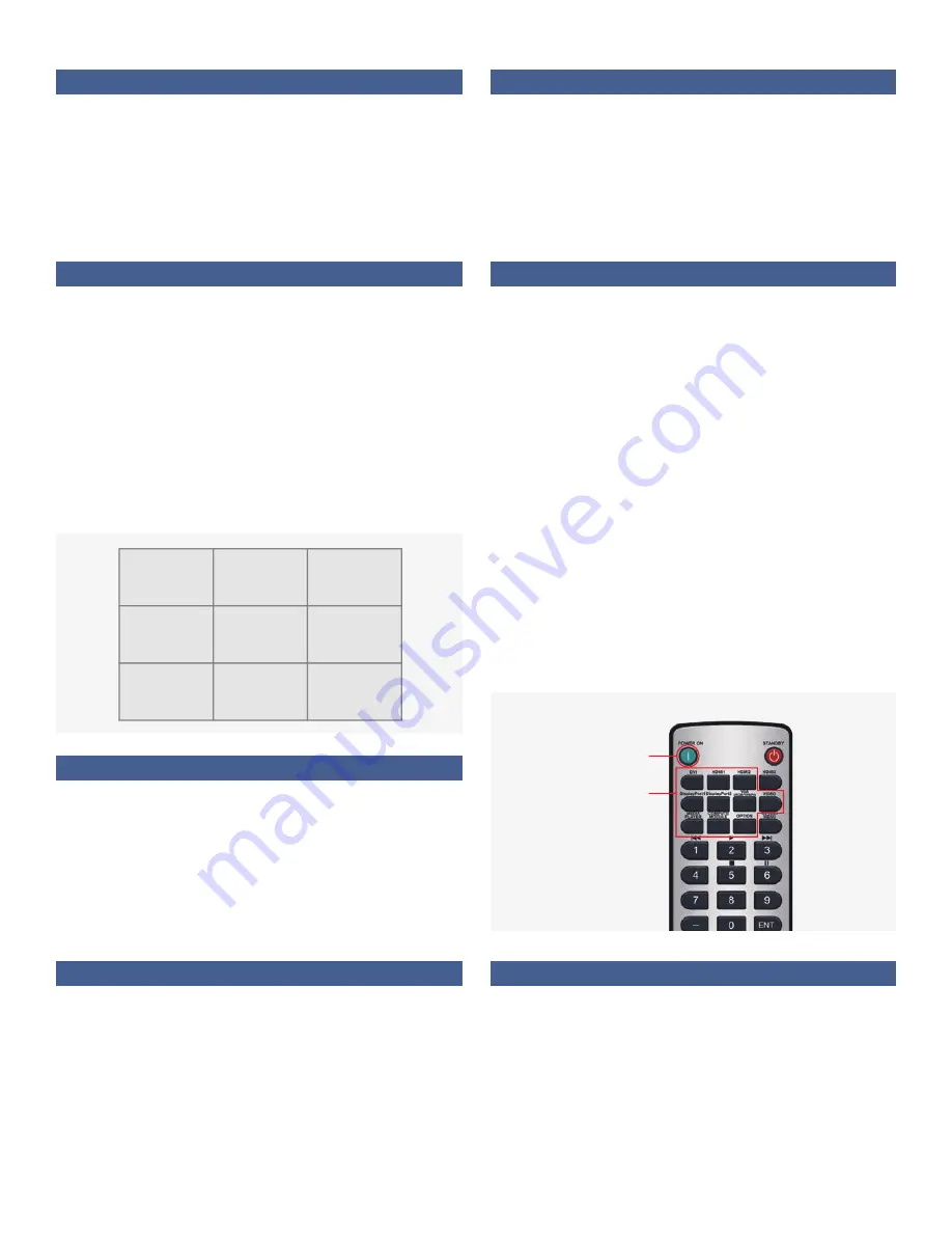
10. Choose input source for all displays
To distribute the video signal from primary monitor across all monitors, each successive
monitor must have DisplayPort1 or HDMI1 as input.
Configure the remote control as ID "0" to manage all screens in parallel
(refer to section 5)
POWER ON the entire video wall (some of the displays may be in auto standby
during configuration).
Choose the preferred INPUT source (DisplayPort1 or HDMI1) for all displays
via the input buttons on the remote control.
Note:
In the case of an OPS Slot-in PC or Media Player input, the first
monitor must be switched to Option or Media Player. In this case, all other
monitors in the Daisy Chain remain DisplayPort1 or HDMI1. For a detailed
Daisy Chain cable mapping table, refer to the chapter “Primary monitor -
input/output mapping” at the beginning of this guide.
13. Copy Settings (Picture settings)
To align all monitors within the video wall with the same application Preset of the first
screen, copy the chosen settings to all monitors.
Menu:
MULTI-DSP > SETTING COPY
Select “PICTURE” > SET
COPY START > YES
8. Auto ID / IP RESET
Monitor ID / IP address reset should be performed on the first monitor.
Menu: MULTI-DSP > ID CONTROL > AUTO ID/IP RESET > SET
Note:
Auto ID Reset must be performed on the first monitor in the LAN daisy chain when
configuration, cabling or monitors are changed or swapped.
ID: 1
ID: 2
ID: 3
ID: 6
ID: 5
ID: 4
ID: 7
ID: 8
ID: 9
192.168.10.1
192.168.10.6
192.168.10.7
192.168.10.2
192.168.10.5
192.168.10.8
192.168.10.3
192.168.10.4
192.168.10.9
INPUT
POWER ON


