background image

English-11

English

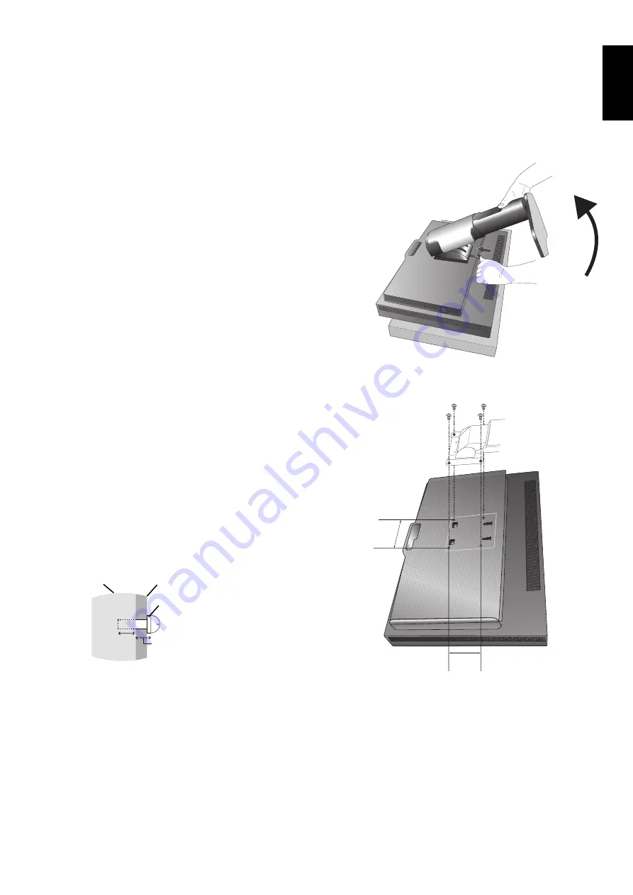
Figure S.1

Mount the Flexible arm

This LCD monitor is designed for use with a fl exible arm.

1.  Follow the instructions on how Remove Monitor Stand for 

Mounting to remove the stand.

2.  Using the attached 4 screws, attach the arm to the monitor 

(

Figure F.1

).

Caution: 

Use ONLY the screws (4 pcs) that are included, M4 size 
screws (Length: thickness of bracket and  
5-7 mm) when mounting to avoid damage to the monitor 
and stand. To fulfi l the safety requirements the monitor 
must be mounted to an arm which guaranties the 
necessary stability under consideration of the weight of 
the monitor. The LCD monitor should only be used with 
an approved arm (e.g. TUEV GS mark).

Mounting
Bracket

Screw

Washer

Unit

5-7 mm

Thickness 
of bracket 
and washer

NOTE: 

Tighten all screws. 
(recommended Fasten Force: 98 - 137N•cm)

Flexible Arm Installation

This LCD monitor is designed for use with a fl exible arm.

To prepare the monitor for alternate mounting purposes:

• 

Follow the instructions provided by the manufacturer of the display mount.

• 

To meet the safety requirements, the monitor must be mounted to an arm that supports the weight of the monitor. 
See page 25 for details. Remove the monitor stand before mounting.

* Contact your dealer for more information.

Remove Monitor Stand for Mounting

To prepare the monitor for alternate mounting purposes:

1.  Disconnect all cables.

2.  Place hands on each side of the monitor and lift up to the highest position.

3.  Place monitor face down on a non-abrasive surface (

Figure S.1

).

Be sure to not apply any stress or pressure to the integrated front sensor. 
To avoid this, lay the monitor face down on a desk or table with the integrated 
front sensor, situated off the edge (

Figure S.1

).

4.  Place one hand around the base and one hand on the Quick Release Lever. 

Push and hold the Quick Release Lever in the direction indicated by the 
arrows (

Figure S.1

).

5.  Lift up the stand to unhook it from the monitor (

Figure S.1

). 

The monitor can now be mounted using an alternate method. 
Reverse the process to reattach stand.

NOTE: 

Handle with care when removing monitor stand.

100 mm

100 mm

Figure F.1

Weight of LCD assembly: 4.8 kg

Summary of Contents for MultiSync MDC212C2

Page 1: ...Medical Display MultiSync MDC212C2 INSTALLATION MAINTENANCE GUIDE ...

Page 2: ...tact with any part inside this unit This symbol alerts the user that important literature concerning the operation and maintenance of this unit has been included Therefore it should be read carefully in order to avoid any problems Protective earth terminal marked Stand by AC Input MEDICAL GENERAL MEDICAL EQUIPMENT AS TO ELECTRICAL SHOCK FIRE AND MECHANICAL HAZARD ONLY IN ACCORDANCE WITH ANSI AAMI ...

Page 3: ... INSIDE REFER SERVICING TO QUALIFIED SERVICE PERSONNEL CAUTION Power Cord Important Information CAUTION Please use the power cord provided with this monitor in accordance with the table below If a power cord is not supplied with this equipment please contact your supplier For all other cases please use a power cord that matches the AC voltage of the power outlet and has been approved by and compli...

Page 4: ...he AC outlet shall be readily available and accessible This device is equipped with an integrated front sensor and ambient light sensor complying with the IEC 62563 1 standard requirements for measurement devices with a calibration traceable to a primary standards laboratory Therefore these sensors can be re calibrated using external luminance and illuminance meters as a reference which were calib...

Page 5: ...ed by turning the equipment off and on the user is encouraged to try to correct the interference by one or more of the following measures Reorient or relocate the receiving antenna Increase the separation between the equipment and receiver Connect the equipment into an outlet on a circuit different from that to which the receiver is connected Consult your dealer or an experienced radio TV technici...

Page 6: ...or Vibration can damage the backlight Do not install where the monitor will be exposed to continual vibration If monitor or glass is broken do not come in contact with the liquid crystal and handle with care To prevent damage to the LCD monitor caused by tipping over due to earthquakes or other shocks make sure to install the monitor in a stable location and take measures to prevent falling Please...

Page 7: ... is highly recommended in order to keep front sensor measurements accurate over time The recommended time interval to re adjust the front sensor is 24 months CORRECT PLACEMENT AND ADJUSTMENT OF THE MONITOR CAN REDUCE EYE SHOULDER AND NECK FATIGUE CHECK THE FOLLOWING WHEN YOU POSITION THE MONITOR For optimum performance during normal operation allow 30 minutes for the display to warm up For re cali...

Page 8: ...ROM Power Cord 1 Quick Reference Guide USB Cable Screws Remember to save your original box and packing material to transport or ship the monitor 1 Type and number of power cords included will depend on the where the LCD monitor is to be shipped When more than one power cord is included please use a power cord that matches the AC voltage of the power outlet and has been approved by and complies wit...

Page 9: ...card in your system Figure A 2 For a PC with DisplayPort output Connect the DisplayPort cable to the connector of the display card in your system Figure A 3 Figure A 1 Figure A 2 Figure A 3 DisplayPort cable NOTE 1 Please use a DisplayPort cable with a DisplayPort logo 2 When removing the DisplayPort cable hold down the top button to release the lock 3 Height adjustment is locked by lock button Pl...

Page 10: ...isplay management the USB cable shipped with the display must be connected with a USB port of the computer as well Figure C 1a A Type B Type A Type B Type B Type Figure C 1 Power cord 30 Tilt DisplayPort DVI D USB downstream USB upstream D SUB Highest Stand Position USB downstream 5 To keep the cables neatly organized place them into the cable management system that is built into the stand Place t...

Page 11: ...or most timings For further adjustments use the following OSD controls AUTO CONTRAST Analog input only AUTO ADJUST Analog input only Refer to the Controls section of this User s Manual for a full description of these OSD controls NOTE If you have any problems please refer to the Troubleshooting section of this User s Manual Figure E 1 Power Button Raise and Lower the Monitor Screen The monitor may...

Page 12: ...unter clockwise from Portrait to Landscape Figure R 1 To rotate OSD menu between landscape and portrait refer to Controls section Figure R 1 Tilt Grasp top and bottom sides of the monitor screen with your hands and adjust the tilt as desired Figure TS 1 Figure TS 1 NOTE Handle with care when tilting the monitor screen NOTE This monitor has the integrated front sensor Do not touch the integrated fr...

Page 13: ...instructions provided by the manufacturer of the display mount To meet the safety requirements the monitor must be mounted to an arm that supports the weight of the monitor See page 25 for details Remove the monitor stand before mounting Contact your dealer for more information Remove Monitor Stand for Mounting To prepare the monitor for alternate mounting purposes 1 Disconnect all cables 2 Place ...

Page 14: ...nu Shows PICTURE MODE Shows the quick screen QA test pattern 2 AMBIENT LIGHT SENSOR Detects the level of ambient light allowing the monitor to make adjustments to various settings Do not cover this sensor See page 20 3 POWER Turns the monitor on and off 4 LED Indicates that power is on 5 Control Buttons A INPUT button SELECT button B EXIT button C LEFT RIGHT button MENU button D UP DOWN button MEN...

Page 15: ... OSD will blink BLACK Adjusts the black luminance When low settings are selected that cannot be displayed the indicator on the OSD will turn magenta CONTRAST Analog input only Adjusts the overall image and background screen brightness by input signal level NOTE It is recommended to use LUMINANCE to adjust screen brightness for lower power consumption and improved image quality AUTO CONTRAST Analog...

Page 16: ...rol Systems PICTURE MODE Changes the Picture mode that is most suitable for the type of content that is shown 5 Picture modes are available to be customized See Advanced menu Tag1 PICTURE MODE page 19 and Using the PICTURE MODE function page 17 for more information Tools VIDEO DETECT Selects the method of video detection when more than one video input is connected FIRST When current video input si...

Page 17: ...You can choose where you would like the OSD control image to appear on your screen Selecting OSD Location allows you to manually adjust the position of the OSD control menu Up or Down OSD TURN OFF The OSD control menu will stay on as long as it is use You can select how long the monitor waits after the last touch of a button to shut off the OSD control menu The preset choices are 10 120 seconds by...

Page 18: ... of your monitor OSD Warning OSD Warning menus disappear with EXIT button NO SIGNAL This function gives a warning when there is no Horizontal or Vertical Sync After power is turned on or when there is a change of input signal the No Signal window will appear OUT OF RANGE This function gives a recommendation of the optimized resolution and refresh rate After the power is turned on or there is a cha...

Page 19: ... The type of PRESET PRESET PURPOSE MEDICAL Factory setting Recommended setting for displaying medical images Gamma 2 2 Medical settings for endoscopic imaging view Setting for Gamma 2 2 image TEXT The conditions are optimal for viewing documents and sRGB images PROGRAMMABLE For Hardware Calibration settings by NEC Display Solutions QA software some OSD settings are disabled NOTE A PICTURE MODE IS ...

Page 20: ...ou may now check the gray levels and the overall quality visually To exit the QA TEST mode press EXIT The image of the video signal source will return If the monitor is not connected with any video signal source Make sure that only the NO SIGNAL message is displayed then press the RESET button for more than 3 seconds This will start drawing the test pattern across the screen then start the DICOM M...

Page 21: ...M LOG LINEAR L Star CUSTOM sRGB and PROGRAMMABLE DICOM DICOM GSDF Grayscale Standard Display Function LOG LINEAR Luminance changes logarhythmically in response to a linear change of gradation L Star GAMMA setting for eciRGB_v2 and Lab color space CUSTOM This is displayed as numerical value which you select The gamma value is selectable within a range between 0 5 and 4 0 with 0 1 intervals sRGB Set...

Page 22: ... No function ON Stabilizes Color NOTE When the function is ON the lifetime of the LUMINANCE setting level will be reduced AMBIENT LIGHT COMP Adjusts the luminance and gamma value to be in user setting value including outside luminance level OFF No ambient light compensation 1 Compensation based on the influence of external light measured during the calibration 2 Compensation based on the influence...

Page 23: ... the image on the screen Press LEFT button to narrow the width of the image on the screen V RESOLUTION Adjusts the vertical size by increasing or decreasing the setting Press RIGHT button to expand the height of the image on the screen Press LEFT button to narrow the height of the image on the screen EXPANSION Sets the zoom method FULL The image is expanded to full screen regardless of the resolut...

Page 24: ...r LED on the monitor LED COLOR 1 Toggles the power LED on the front between blue or green Tag7 LANGUAGE 1 OSD control menus are available in nine languages Press LEFT or RIGHT to select OSD H POSITION You can choose where you would like the OSD control image to appear on your screen Selecting OSD Location allows you to manually adjust the position of the OSD control menu left or right OSD V POSITI...

Page 25: ...cursor horizontally Use the Down or Up buttons to up down schedule number date and time A square mark next to the number of the schedule indicates that the selected schedule is in effect enable disable INTERVAL Set the frequency with wich the schedule will be executed days weeks months and weeks per month When you set 0 the schedule works once NOTE When a schedule overlaps the schedule from the la...

Page 26: ...an all white screen TEMPERATURE 1 Current internal temperature is shown in degrees C BACKLIGHT LIFETIME 1 The estimated remaining lifetime of the display backlight is indicated here Backlight lifetime depends mainly on the desired calibrated settings The lower the calibrated setting the longer the backlight s estimated lifetime HOURS RUNNING 1 Shows total running time ILLUMINANCE 1 Shows the lux v...

Page 27: ...2 mm 17 0 inches USB Hub I F Port Load Current USB Specification Revision 3 0 Upstream 1 Downstream 3 Maximum 0 9 A per port Power Supply AC 100 240 V 50 60 Hz Current Rating 1 0 0 6 A with option Dimensions Landscape Portrait Height Adjustment 466 4 mm W x 374 6 524 6 mm H x 227 6 mm D 18 4 inches W x 14 7 20 7 inches H x 9 0 inches D 359 0 mm W x 484 0 580 0 mm H x 227 6 mm D 14 1 inches W x 19 ...

Page 28: ...etup and installation by allowing the monitor to send its capabilities such as screen size and resolutions supported directly to your computer automatically optimizing display performance Intelligent Power Manager System Provides innovative power saving methods that allow the monitor to shift to a lower power consumption level when on but not in use saving two thirds of your monitor energy costs r...

Page 29: ... and SELECT INPUT buttons at the same time This will reset all color parameters to the factory setting This reset will take about 10 seconds and then the factory settings screen is displayed Message OUT OF RANGE is displayed screen is either blank or shows rough images only Image is displayed only roughly pixels are missing and OSD warning OUT OF RANGE is displayed Either signal clock or resolutio...

Page 30: ...ice to qualified personnel for service USB Hub does not operate Check to make sure the USB cord is properly connected Refer to your USB device User s Manual Turn the Power button off and on again Human sensor does not work Make sure there is human presence in front of the monitor Make sure there is no object in front of Human sensor Make sure there is no equipment which radiating infrared rays in ...

Page 31: ...minimum of 30 minutes If Stand Alone calibration is started before the monitor is warmed up a warning will appear on screen Figure A 1 NOTE Refer to the KEY MAP Figure A 2 to adjust the settings for calibration Stand Alone calibration should be performed in either portrait or landscape orientation NOTE To start calibration without a computer perform the following steps When the NO SIGNAL message a...

Page 32: ...panel Figure S 2 Place the external near range color analyzer in the center of the display panel then press SELECT NOTE Place an external near range color analyzer flat against the LCD to avoid any influence of ambient light DO NOT press an external near range color analyzer against the display panel 4 The measument screen will be displayed Measure the luminance and chromaticity value of the cente...

Page 33: ...n Gamma Adjust is performed 1 To show the CALIBRATION menu select the STAND ALONE CALIBRATION in the advanced menu page 24 2 Select GAMMA ADJUST in the MODE selection Figure 1 3 Press SELECT to start the calibration This may take several minutes depending on user setting Figure 1 4 GAMMA Measurement is continuously executed automatically After completing GAMMA Measurement you can set DATE and TIME...

Page 34: ...ng is 1 or 2 Please perform AMBIENT SENSOR CALIBRATION in the following cases The usage environment has changed NOTE Please execute the Ambient Sensor Calibration under indirect light AMBIENT SENSOR CALIBRATION requires an illuminance meter and a telescopic luminance meter 1 In power off mode measure the luminance value of the center of the screen by the telescopic luminance meter If a telescopic ...

Page 35: ...having measured press SELECT without changing the value 6 After the CALIBRATION SUCCEEDED message appears Figure AS 4 press SELECT You can set DATE and TIME by using control keys and press SELECT 7 To end the calibration mode press EXIT Figure AS 4 Figure AS 3 Illuminance meter Figure AS 5 ...

Page 36: ...d The monitor enters a single Energy Saving mode Mode Power consumption LED colour Normal Operation with option Approx 54 W Green or blue Energy Saving Mode Less than 6 W Amber Off Mode Less than 0 3 W Unlit For additional information visit http www necdisplay com in USA http www nec display solutions com in Europe http www nec display com global index html Global WEEE Mark European Directive 2012...

Reviews: