background image

English-2

Canadian Department of Communications Compliance
Statement

DOC: 

This Class B digital apparatus meets all requirements of the Canadian Interference-Causing Equipment Regulations.

C-UL:

 Bears the C-UL Mark and is in compliance with Canadian Safety Regulations according to CAN/CSA C22.2 No. 60950-1.

FCC Information

1.

Use the attached specified cables with the MultiSync LCD1970GX (L194RH) colour monitor so as not to interfere with
radio and television reception.

(1)

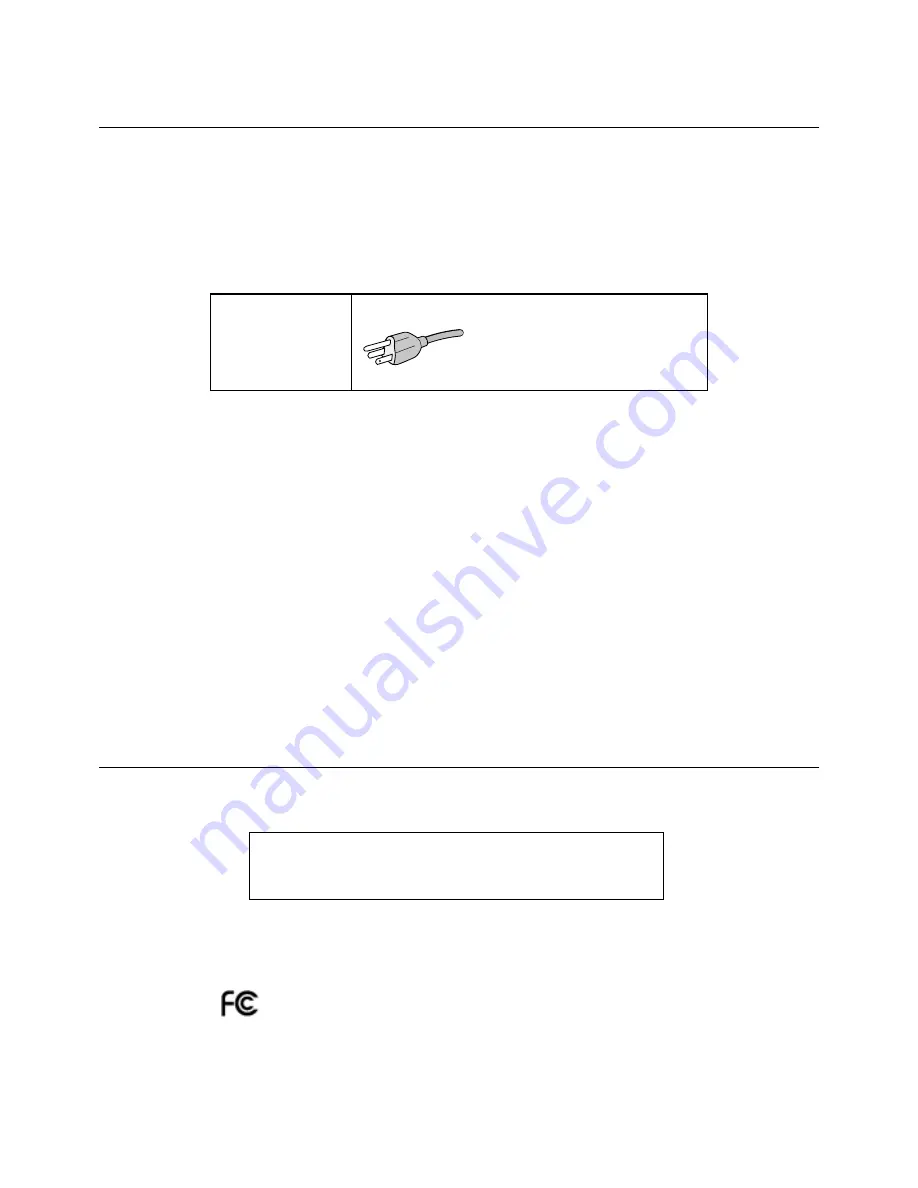
The power supply cord you use must have been approved by and comply with the safety standards of U.S.A.,
and meet the following condition.

Power supply cord

Non shield type, 3-conductor

Length

2.0 m

Plug shape

U.S.A

(2)

Please use the supplied shielded video signal cable. Use of other cables and adapters may cause interference
with radio and television reception.

2.

This equipment has been tested and found to comply with the limits for a Class B digital device, pursuant to part 15 of
the FCC Rules. These limits are designed to provide reasonable protection against harmful interference in a residential
installation. This equipment generates, uses, and can radiate radio frequency energy, and, if not installed and used in
accordance with the instructions, may cause harmful interference to radio communications. However, there is no
guarantee that interference will not occur in a particular installation. If this equipment does cause harmful interference
to radio or television reception, which can be determined by turning the equipment off and on, the user is encouraged
to try to correct the interference by one or more of the following measures:

Reorient or relocate the receiving antenna.

Increase the separation between the equipment and receiver.

Connect the equipment into an outlet on a circuit different from that to which the receiver is connected.

Consult your dealer or an experienced radio/TV technician for help.

If necessary, the user should contact the dealer or an experienced radio/television technician for additional
suggestions. The user may find the following booklet, prepared by the Federal Communications Commission, helpful:
“How to Identify and Resolve Radio-TV Interference Problems.” This booklet is available from the U.S. Government
Printing Office, Washington, D.C., 20402, Stock No. 004-000-00345-4.

Declaration of Conformity

This device complies with Part 15 of FCC Rules. Operation is subject to the following two conditions. (1) This device may not
cause harmful interference, and (2) this device must accept any interference received, including interference that may cause
undesired operation.

U.S. Responsible Party:

NEC Display Solutions of America, Inc.

Address:

500 Park Blvd, Suite 1100
Itasca, Illinois 60143

Tel. No.:

(630) 467-3000

Type of Product:

Display Monitor

Equipment Classification:

Class B Peripheral

Model:

MultiSync LCD1970GX (L194RH)

We hereby declare that the equipment specified above conforms

to the technical standards as specified in the FCC Rules.

Summary of Contents for MultiSync LCD1970GX LCD1970GX LCD1970GX

Page 1: ...MultiSync LCD1970GX User s Manual ...

Page 2: ...iance Statement English 2 Declaration of Conformity English 2 Contents English 3 Quick Start English 4 Controls English 8 Recommended use English 10 Specifications English 12 Features English 13 Troubleshooting English 14 TCO 03 English 15 Manufacturer s Recycling and Energy Information English 16 ...

Page 3: ...OR SHOCK HAZARDS DO NOT EXPOSE THIS UNIT TO RAIN OR MOISTURE ALSO DO NOT USE THIS UNIT S POLARIZED PLUG WITH AN EXTENSION CORD RECEPTACLE OR OTHER OUTLETS UNLESS THE PRONGS CAN BE FULLY INSERTED REFRAIN FROM OPENING THE CABINET AS THERE ARE HIGH VOLTAGE COMPONENTS INSIDE REFER SERVICING TO QUALIFIED SERVICE PERSONNEL Declaration Declaration of the Manufacturer We hereby certify that the colour mon...

Page 4: ...on If this equipment does cause harmful interference to radio or television reception which can be determined by turning the equipment off and on the user is encouraged to try to correct the interference by one or more of the following measures Reorient or relocate the receiving antenna Increase the separation between the equipment and receiver Connect the equipment into an outlet on a circuit dif...

Page 5: ...ncludes complete User s Manual in PDF format To see the User s Manual Acrobat Reader 4 0 or higher must be installed on your PC Power Cord User s Manual 15 pin mini D SUB male to 15 pin mini D SUB male CD ROM USB Cable Remember to save your original box and packing material to transport or ship the monitor Cable cover NOTE This monitor can be equipped with optional loudspeakers MultiSync Sound bar...

Page 6: ... 30 degree angle and lift up to the highest position Figure C 1 4 Connect all cables to the appropriate connectors Figure C 1 Using the USB cable connect the B type connector to the USB upstream port on the bottom side of the monitor and A type connector to the downstream port on the computer Figure B 2 If you can use the cord from the USB device use one of the downstream ports on the side of the ...

Page 7: ...h on the back side of the monitor must be turned on Figure E 1 Turn on the monitor with the front power button and the computer NOTE The vacation switch is a true on off switch If this switch is on the OFF position the monitor cannot be turned on using the front button DO NOT switch on off repeatedly 12 No Touch Auto Adjust automatically adjusts the monitor to optimal settings upon initial setup f...

Page 8: ...ing and swivelling the monitor screen Figure TS 1 Figure S 2 Remove Monitor Stand for Mounting To prepare the monitor for alternate mounting purposes 1 Place hands on each side of the monitor and lift up to the highest position Remove the cable cover Figure S 1 NOTE If you have difficulty removing the cable cover please push the lower opening upward to remove it as shown in the figure beside 2 Dis...

Page 9: ... Installation This LCD monitor is designed for use with a flexible arm To mount the monitor to a flexible arm 1 Follow the instructions on how Remove Monitor Stand for Mounting to remove the stand 2 Using the 4 screws from the stand removal and attach the arm to the monitor Figure F 1 NOTE The LCD monitor should only be used with an approved arm e g GS mark To meet the safety requirements the moni...

Page 10: ...the Image Position H Size and Fine settings Image Controls Analog input only LEFT RIGHT Controls Horizontal Image Position within the display area of the LCD DOWN UP Controls Vertical Image Position within the display area of the LCD H SIZE Adjusts the horizontal size by increasing or decreasing this setting FINE Improves focus clarity and image stability by increasing or decreasing this setting M...

Page 11: ...SM control image to appear vertically on your screen OSM Turn Off The OSM control menu will stay on as long as it is in use In the OSM Turn Off submenu you can select how long the monitor waits after the last touch of a button to shut off the OSM control menu OSM Lock Out This control completely locks out access to all OSM control functions without Brightness and Contrast When attempting to activa...

Page 12: ... have fallen into the monitor If the monitor has been exposed to rain or water If the monitor has been dropped or the cabinet damaged If the monitor does not operate normally by following operating instructions If glass is broken handle with care If monitor or glass is broken do not come in contact with the liquid crystal and handle with care Allow adequate ventilation around the monitor so that h...

Page 13: ...position the Contrast control to its maximum setting Use the preset Size and Position controls with standard signals Use the preset Colour Setting Use non interlaced signals with a vertical refresh rate between 60 75 Hz Do not use primary colour blue on a dark background as it is difficult to see and may produce eye fatigue to insufficient contrast Cleaning the LCD Panel Recommended cleaning of th...

Page 14: ... SOLUTIONS cites recommended resolution at 60 Hz for optimal display performance Active Display Area Horizontal 376 3 mm 14 8 inches Vertical 301 1 mm 11 9 inches USB Hub I P USB Specification Revision 2 0 Port Upstream 1 Downstream 4 Load Current Maximum 0 5A per port Power Supply AC 100 240V 50 60Hz Power Consumption 52W typ without optional Sound Bar Current Rating 1 2 0 6A Dimensions 412 5 mm ...

Page 15: ...s for quick and easy image adjustments tilt base for preferred angle of vision small footprint and compliance with MPRII and TCO guidelines for lower emissions Plug and Play The Microsoft solution with the Windows 95 98 Me 2000 XP operating system facilitates setup and installation by allowing the monitor to send its capabilities such as screen size and resolutions supported directly to your compu...

Page 16: ...ains the monitor should be turned off for one hour to erase the image NOTE As with all personal display devices NEC DISPLAY SOLUTIONS recommends displaying moving images and using a moving screen saver at regular intervals whenever the screen is idle or turning off the monitor when not in use Image is unstable unfocused or swimming is apparent Signal cable should be completely attached to the comp...

Page 17: ...ergy Energy saving mode after a certain time beneficial both for the user and the environment Electrical safety Emissions Electromagnetic fields Noise emissions Ecology The product must be prepared for recycling and the manufacturer must have a certified environmental management system such as EMAS or ISO 14 001 Restrictions on chlorinated and brominated flame retardants and polymers heavy metals ...

Page 18: ...A Display Power Management Signaling DPMS Standard signal is sent to the monitor the Energy Saving mode is activated The monitor enters a single Energy Saving mode Mode Power consumption LED colour Normal Operation Approx 52W Green Energy Saving Mode Less than 4W Amber Off Mode Less than 2W Unlit Disposing of your old NEC product Within the European Union EU wide legislation as implemented in each...

Reviews: