background image

3

Quick Start

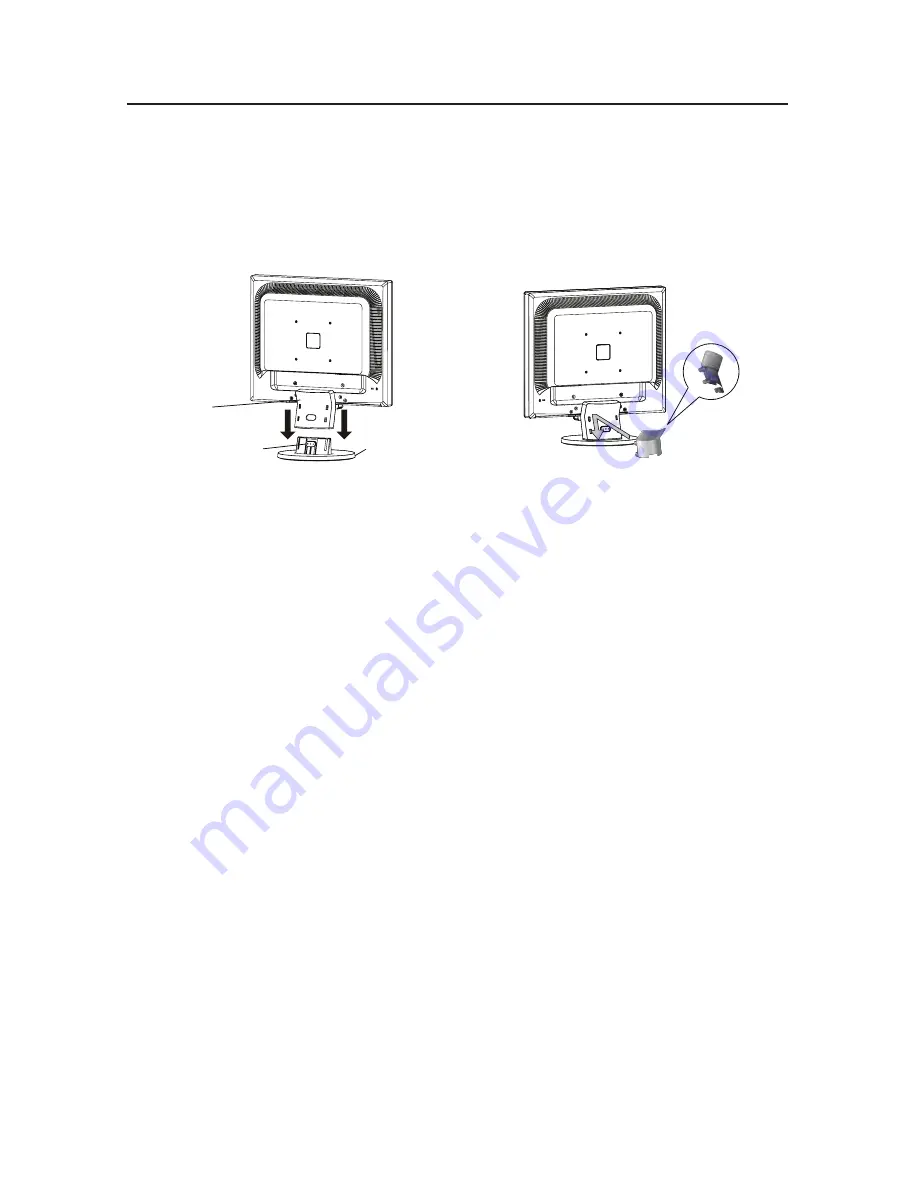
To attach the Base to the LCD Stand:

.  Insert the front of the LCD Stand into the holes in the front of the Base 

(Figure 1)

.

2.  Attach the Base to the Stand. The locking tab on the Base should fit into the hole on the back  

  of the Stand. 
3. Attach the Cable Holder onto the Base 

(Figure 2)

. Insert the hooks on the Cable Holder into 

  the holes at the back of the Stand and slide the Cable Holder downward into place.

Locking Tab

Base 

Stand

Figure 

Figure 2

To attach the MultiSync LCD monitor to your system, follow these instructions:

. Turn off the power to your computer.
2. For the PC or MAC with DVI digital output: Connect the DVI signal cable (not included) to the 

connector of the display card in your system (

Figure A.1

). Tighten all screws.

  For the PC with Analog output: Connect the 5-pin mini D-SUB signal cable to the connector 

of the display card in your system 

(Figure A.2)

.  Tighten all screws.

  For the MAC: Connect the MultiSync Macintosh cable adapter to the computer, then attach 

the 5-pin mini D-SUB signal cable to the MultiSync Macintosh cable adapter 

(Figure A.3)

Tighten all screws.

  NOTE:  To obtain the MultiSync Macintosh cable adapter, call  

  NEC Display Solutions of America, Inc. at (800) 632-4662.

3. Connect the cables to the appropriate connector on the back of the monitor 

(Figure B.1)

  NOTE:  If  you  use  this  monitor  at  AC125-240V,  please  refer  to  Recommended  Use 


section of this manual for proper selection of power cord.

4. Connect one end of the power cord to the LCD and the other end to the power outlet. Place the 

video signal cable, power cord and DVI cable into the cable holder 

(Figure B.1)

.  

NOTE:  Adjust the position of cables in the cable holder to avoid damage.
NOTE:  If  you  use  this  monitor  at  AC125-240V,  please  refer  to  Recommended  Use  

section of this manual for proper selection of power cord.

5. Turn on the monitor with the front power button and the computer. 

(Figure C.1)

6. No-touch Auto Adjust automatically adjusts the monitor to optimal settings upon initial    

setup for most timings. For further adjustments, use the following OSM

®

 controls:

  • Auto Adjust Contrast      • Auto Adjust
  Refer  to  the  Controls  section  of  this  User’s  Manual  for  a  full  description  of  these  

  OSM controls.

  NOTE:

  For  download  information  on  the  Windows

®

  95/98/Me/2000/XP  INF  file  for  


your MultiSync  monitor, refer to the 

References

 section of this User’s Manual.

  NOTE:

  If  you  have  any  problems,  please  refer  to  the 

Troubleshooting

  section  of  this  


User’s Manual.

Summary of Contents for MultiSync 1740CX

Page 1: ...USER S MANUAL MultiSync 1740CX 1940CX To learn about other special offers register online at www necdisplay com...

Page 2: ...ifications 12 Features 14 Troubleshooting 15 References 16 Limited Warranty 17 TCO 99 18 Avertissement 21 Contenu 22 Mise en marche rapide 23 Commandes 27 Usage recommand 30 Fiche technique 32 Fonctio...

Page 3: ...designed to provide reason able protection against harmful interference in a residential installation This equipment generates uses and can radiate radio frequency energy and if not installed and use...

Page 4: ...l to transport or ship the monitor Your new NEC MultiSync LCD monitor box should contain the following MultiSync LCD monitor Power Cord User s Manual Video Signal Cable Base Stand Cable Holder MultiSy...

Page 5: ...tiSync Macintosh cable adapter call NEC Display Solutions of America Inc at 800 632 4662 3 Connect the cables to the appropriate connector on the back of the monitor Figure B 1 NOTE If you use this mo...

Page 6: ...d Note Some Macintosh systems do not require a Macintosh Cable Adapter Figure A 2 Figure C 1 Figure A 3 Macintosh Cable Adapter not included Figure B 1 Input VGA Cable holder Power button Power Cable...

Page 7: ...nonabrasive surface Figure R 1 3 Remove the 4 screws connecting the monitor to the stand and slide the stand off from the LCD Figure R 1 The monitor is now ready for mounting in an alternate manner 4...

Page 8: ...in the picture when installing To meet the safety requirements the monitor must be mounted to an arm which guaranties the necessary stability under consideration of the weight of the monitor The LCD m...

Page 9: ...moves left Cursor moves right OSM On Adjustment stage Go to Icon selection stage Decrease Value or Move Cursor left Increase value or Move Cursor right Reset operation SELECT 1 2 RESET 1 Basic key fu...

Page 10: ...g or decreasing this setting FINE Analog Input Only Improves focus clarity and image stability by increasing or decreasing this setting COLOR CONTROL SYSTEMS Four color presets 9300 7500 6500 USER sel...

Page 11: ...ecting EXIT allows you exit OSM menu sub menu LANGUAGE OSM control menus are available in seven languages OSM TURN OFF The OSM control menu will stay on as long as it is in use In the OSM Turn OFF sub...

Page 12: ...e humid dusty or oily areas If glass is broken handle with care Do not cover vent on monitor Immediately unplug your monitor from the wall outlet and refer servicing to qualified service person nel un...

Page 13: ...signals with a vertical refresh rate between 60 75Hz Do not use primary color blue on a dark background as it is difficult to see and may produce eye fatigue to insufficient contrast Cleaning the LCD...

Page 14: ...IONS cites 1280 x 960 1 at 60 Hz to 75 Hz recommended resolution at 60 Hz for 1280 x 1024 at 60 Hz to 75 Hz optimal display performance Active Display Area Horizontal 338 0 mm 13 3 inches Vertical 270...

Page 15: ...SOLUTIONS cites 1280 x 960 1 at 60 Hz to 75 Hz recommended resolution at 60 Hz for 1280 x 1024 at 60 Hz to 75 Hz optimal display performance Active Display Area Horizontal 376 0 mm 14 8 inches Vertica...

Page 16: ...le of vision small footprint and compliance with MPRII and TCO guidelines for lower emissions Plug and Play The Microsoft solution with the Windows 95 98 Me 2000 XP operat ing system facilitates setup...

Page 17: ...hould be turned off for one hour to erase the image NOTE As with all personal display devices NEC Display Solutions of America Inc recommends displaying moving images and using a moving screen saver a...

Page 18: ...y com Online Technical Support www necdisplay com Sales and Product Information Sales Information Line 888 632 6487 Canadian Customers 866 771 0266 Ext 4037 Government Sales 800 284 6320 Government Sa...

Page 19: ...turned to NEC DISPLAY SOLUTIONS for service MUST have prior approval which may be obtained by calling 1 800 632 4662 The Product shall not have been previously altered repaired or serviced by anyone o...

Page 20: ...elling scheme was developed as a joint effort by the TCO The Swedish Confederation of Professional Employees Svenska Naturskydd sforeningen The Swedish Society for Nature Conservation and Statens Ener...

Page 21: ...metimes found in batteries relays and switches Mercury damages the nervous system and is toxic in high doses TCO 99 requirement states that batteries may not contain any Mercury It also demands that n...

Page 22: ...e follow any agreements made between yourself and NEC The mark on electrical and electronic products only applies to the current European Union Member States Outside the European Union If you wish to...

Page 23: ...uillez utiliser le c ble de signal vid o blind fourni L utilisation d autres c bles et adaptateurs peut provoquer des interf rences avec la r ception radio et t l vision 2 Cet appareil a t test et s a...

Page 24: ...e l utilisateur C ble pour le signal vid o Support de base Trous l avant de la base Ne pas oublier de conserver la bo te et le mat riel d emballage d origine pour transporter ou exp dier le moniteur C...

Page 25: ...ous les c bles leurs connecteurs appropri s sur le moniteur Figure B 1 REMARQUE Si vous utilisez ce moniteur 125 CA 240 V veuillez vous reporter la section Utili sation recommand e de ce manuel pour s...

Page 26: ...on d alimentaion Remarque Certains syst mes Macintosh ne n cessitent pas un ad aptateur de c ble Macintosh Adaptateur Macintosh non fourni Figure A 1 Figure C 1 Figure A 2 Figure B 1 Input VGA Cordon...

Page 27: ...Placez le moniteur avec l cran vers le bas sur une surface non abrasive Figure R 1 3 Enlever les 4 vis qui fixent le moniteur au support et enlever la plaque m tallique Figure R 1 Vous pouv z pr sent...

Page 28: ...vec un bras flexible Utiliser les vis fournies 4pi ces lors de l installation comme indiqu sur la figure Le moniteur doit tre install sur un bras garantissant la stabilit n cessaire correspon dant au...

Page 29: ...s sur l avant du moniteur fournissent les fonctions suivantes OSM affich Raccourci la fen tre de r glage de luminosit Button Arr t OSM Choisissez le signal d entr e OSM en marche tage de s lection d...

Page 30: ...e la mise au point la nettet et la stabilit de l image en aug men tant ou en diminuant la valeur Fin SYST MES DE CONTR LE DES COULEURS Quatre pr r glages de couleurs 9300 7500 6500 UTILISATEUR s lecti...

Page 31: ...e r solution appara t de 30 secondes apr s la non reconnassance du signal d entr e en tant que signal la r solution optimale MONITOR INFO Le num ro du mod le et le num ro de s rie y sont indigu s Aver...

Page 32: ...e hautes temp ratures humides poussi reuses pr s d huile ou Regal toujours glass sur soin Ne couvre pas l armoire fente ou usage rayonnai mauvaise chaleur D brancher imm diatement le moniteur de la pr...

Page 33: ...ommandes de format et position pr programm es avec signaux standard Utiliser le r glage couleur et les commandes gauche droite pr programm s Utiliser des signaux non entrelac s avec fr quence de rafra...

Page 34: ...optimales et couleurs Zone d affichage active Horizontale 338 0 mm 13 3 pouces Verticale 270 0 mm 10 6 pouces Alimentation 100 240 V 50 60 Hz Tension d alimentation 0 6 0 4 A 100 240V Dimensions Pays...

Page 35: ...75 Hz optimales et couleurs Zone d affichage active Horizontale 376 0 mm 14 8 pouces Verticale 301 0 mm 11 9 pouces Alimentation 100 240 V 50 60 Hz Tension d alimentation 0 8 0 5A 100 240V Dimensions...

Page 36: ...nformit aux directives MPRII et TCO concernant les r ductions d missions Plug and Play La solution Microsoft avec le syst me d exploitation Windows 95 98 Me 2000 XP facilite la configuration et l inst...

Page 37: ...r hors tension pendant une heure pour effacer l image NOTA Comme pour tous les quipements d affichage personnels NEC Display Solutions of America Inc recommande l utilisation d un conomiseur d cran mo...

Page 38: ...stance technique en ligne www necdisplay com Ventes et information produit Ligne d information sur les ventes 888 888 632 6487 Client le canadienne 866 771 0266 Ext 4037 Ventes au gouvernement 800 284...

Page 39: ...z d abord obtenir une autorisation de retour de marchandise en composant le 1 800 632 4662 Le produit ne pourra avoir t enlev ou modifi r par ou entretenu au pr alable par personne d autre que du pers...

Page 40: ...ordinateurs personnels La directive d tiquetage a t labor e par le TCO Conf d ration su doise des employ s professionnels Svenska Naturakyddsforeningen Soci t su doise de conservation de la nature et...

Page 41: ...ants lectriques ou lectroniques ne doivent pas contenir de cad mium Mercure Le mercure est parfois pr sent dans les batteries les relais les interrupteurs et les syst mes r tro clair s Le cadmium s at...

Page 42: ...it en question Vous pouvez aussi respecter tout accord pass entre NEC et vous m me Ie cas ch ant Ce symbole pr sent sur les produits lectriques et lectroniques ne s applique qu aux membres actuels de...

Page 43: ...ujettes modifications sans pr avis La reproduction totale ou partielle de ce document sans l accord pr alable de NEC Display Solutions of America Inc est interdite D CLARATION DE CONFORMIT Cet apparei...

Page 44: ...change at any time without notice Reproduction of this document or portions thereof without prior approval of NEC Display Solutions of America Inc is prohibited DECLARATION OF CONFORMITY This device c...

Reviews: