background image

English-8

Quick Start

To connect the LCD monitor to your system, follow these instructions:

NOTE:  

Make sure to read “Recommended Use” before installation.
In order to display the maximum resolution, a display controller that can output a resolution of 2048 x 2560 is needed.

1.  Turn off the power to your computer.
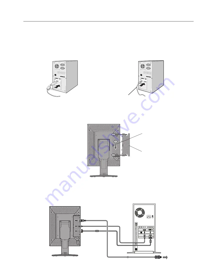
2. 

For a PC with DVI digital output:

 Connect the DVI signal cable to the connector of the display controller in your system 

(

Figure A.1

). Tighten all screws.


For a PC with DisplayPort output: 

Connect the DisplayPort cable to the connector of the display controller in your system 

(

Figure A.2

).

Figure A.1

Figure A.2

DisplayPort cable

NOTE:  

1.  Please use a DisplayPort cable with a DisplayPort logo.
2.  When removing the DisplayPort cable, hold down the top button to release the lock.

3.  Remove the cable cover (

Figure B

). 


To remove the cable cover, unlock the slide latch (1) on the cable cover (2) and slide the cover to the side to remove it.

Figure B

Cable cover

Slide latch

4.  Connect all cables to the appropriate connectors (

Figure C

).

NOTE: 

Incorrect cable connections may result in irregular operation, damage display quality/components of LCD module 
and/or shorten the module’s life.

Figure C

AC  IN

Display Backside

Computer

To the wall outlet

Summary of Contents for MD211G5

Page 1: ...MD211G5...

Page 2: ...and or registered trademarks of Microsoft Corporation in the United States and or other countries VESA is a trademark of the Video Electronics Standard Association All other products and company name...

Page 3: ...English...

Page 4: ...mportant literature concerning the operation and maintenance of this unit has been included Therefore it should be read carefully in order to avoid any problems Protective earth terminal marked Stand...

Page 5: ...ed by turning the equipment off and on the user is encouraged to try to correct the interference by one or more of the following measures Reorient or relocate the receiving antenna Increase the separa...

Page 6: ...NO USER SERVICEABLE PARTS INSIDE REFER SERVICING TO QUALIFIED SERVICE PERSONNEL CAUTION Power Cord Important Information CAUTION Please use the power cord provided with this display in accordance with...

Page 7: ...y available and accessible EMC Precaution This product requires special EMC precautions and needs to be installed and used according to the following information Use the specified cable Using other ca...

Page 8: ...cover vent on monitor Vibration can damage the backlight Do not install the monitor where it will be exposed to continual vibration If the monitor s LCD panel is broken do not come in contact with the...

Page 9: ...monitor no closer than 40 cm 15 75 inches and no further away than 70 cm 27 56 inches from your eyes The optimal distance is 50 cm 19 69 inches Rest your eyes periodically by focusing on an object at...

Page 10: ...le 1 DisplayPort cable Power Cord 2 Quick Reference Guide USB Cable Remember to save your original box and packing material to transport or ship the monitor 1 Dual link DVI cable 2 Type and number of...

Page 11: ...cable to the connector of the display controller in your system Figure A 2 Figure A 1 Figure A 2 DisplayPort cable NOTE 1 Please use a DisplayPort cable with a DisplayPort logo 2 When removing the Di...

Page 12: ...es NOTE Handle with care when raising lowering rotating or tilting the monitor screen 8 Connect one end of the power cord to the AC inlet on the back of the monitor and the other end to the power outl...

Page 13: ...operating state 3rd click DICOM conformance test 4th click OSD off otherwise OSD disappears in 15 sec 6 minus Button Same as plus Button 7 Main power switch Main power supply switch OSD On Screen Dis...

Page 14: ...Pa Dimensions weight Net W x H x D Packed 390 x 487 8 584 x 227 6 mm W x H x D Portrait approx 11 8 kg 475 x 705 x 345 mm W x H x D approx 15 8 kg Safety certifications ANSI AAMI ES60601 1 2005 CAN CS...

Page 15: ...cd m2 Gamma Remark Maximum Minimum Ambient 1 500 1 0 0 0 DICOM Default 2 550 1 0 0 0 DICOM 3 400 1 0 0 0 DICOM The configuration 1 parameter may be modified anytime by a new display calibration NOTE...

Page 16: ...owing the procedure mentioned below 1 The buttons are located in the back of the display Press either button twice and the present operating state appears Present operating state 2 With the present op...

Page 17: ...f the monitor twice to display the PRESENT STATE OSD A display like this picture opens on the screen 2 With the present operating state displayed press and hold both the buttons for 2 seconds The swit...

Page 18: ...SDF Gamma setting Present operating state P R E S E N T S T A T E L U M I N A N C E 5 0 1 A MB L I G H T 3 0 0 lx I N P U T D i s p l a y P o r t C A L I B R A T I O N S E T T I N G C O N F I G 1 L U...

Page 19: ...nced OSD Controls without video input If no video signal is available the display enters the power save mode and the OSD cannot be displayed In this case please follow the procedure below 1 Confirm th...

Page 20: ...ld damage the internal parts If they are too short the connection becomes loose and the display could fall out Mounting plate thickness Screw size 1 5 4 0mm ISO M4x16 CAUTION How to attach wall mounts...

Page 21: ...ttp www nec display solutions com in Europe http www nec display com in Japan or http www necdisplay com in USA Energy Saving This monitor features an advanced energy saving capability Mode Power cons...

Page 22: ...lay Solutions of America 500 Park Blvd Suite 1100 Itasca Illinois 60143 USA Phone 1 630 467 3000 Fax 1 630 467 3010 NEC Display Solutions Europe GmbH Landshuter Allee 12 14 D 80637 Muenchen Germany Ph...

Reviews: