background image

English-8

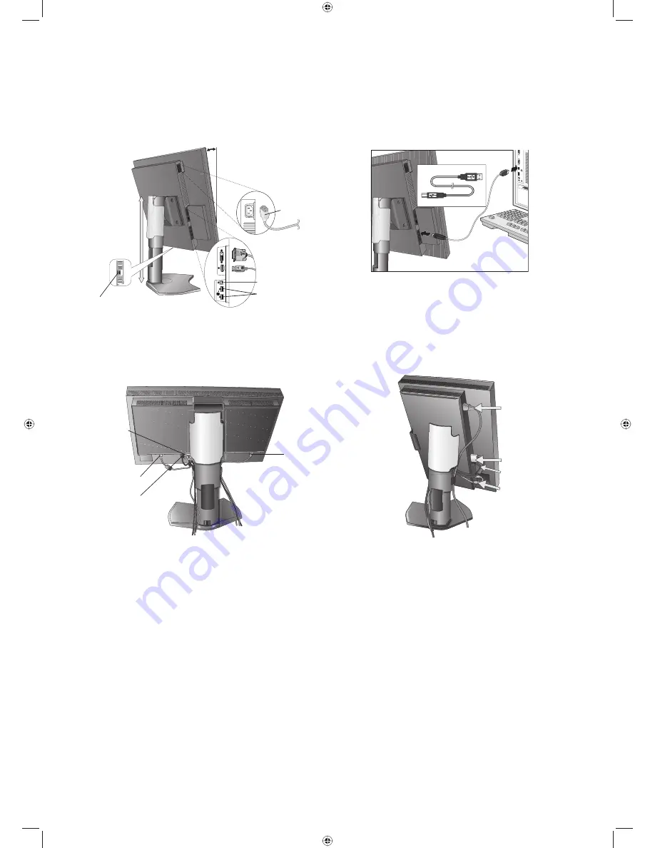
4.  Connect all cables to the appropriate connectors (Figure C.1). When using the USB cable, connect the B type connector 

to the USB upstream port on the right back side of the monitor and the A type connector to the downstream port on the 
computer (Figure C.1a). If using the cord from a USB device, plug into one of the downstream ports of the monitor. 

NOTE: 

Incorrect cable connections may result in irregular operation, damage display quality/components of the LCD module 
and/or shorten the module’s life.

NOTE: 

Up to 5 sub monitors can be daisy-chained.

Figure C.1

Highest 

Stand 

Position

Power cord

30° Tilt

Figure C.1a

A Type

B Type

A Type

B Type

Sensor Port*

1

DVI-D Cable

DisplayPort Cable

USB Upstream Port

USB Downstream Port

5.  To keep the cables neatly organized, place them into the cable management system that is built into the stand.


Place the cables in the hooks fi rmly and evenly (Figure C.2 and Figure C.3).

6.  Please check that you can still rotate, raise and lower the monitor screen when you have installed the cables.

Figure C.2

Figure C.3

USB Cable

Power Cord

DVI-D Cable

Power Cord

DVI-D Cable

USB Cable

DisplayPort 

Cable

DisplayPort Cable

*1  Connect the optional USB optical sensor to this port for self calibration. (See page 25, CD-ROM Version)

MD211G3 paper manual.indb   8

MD211G3 paper manual.indb   8

3/27/12   11:18:31 AM

3/27/12   11:18:31 AM

Summary of Contents for MD211G3

Page 1: ...MD211G3 MD211G3 paper manual indb 1 MD211G3 paper manual indb 1 3 27 12 11 18 27 AM 3 27 12 11 18 27 AM...

Page 2: ...ause harmful interference to radio or television reception which can be determined by turning the equipment off and on the user is encouraged to try to correct the interference by one or more of the f...

Page 3: ...rgy Saving This monitor features an advanced energy saving capability When a VESA Display Power Management Signalling DPMS Standard signal is sent to the monitor the Energy Saving mode is activated Th...

Page 4: ...MD211G3 paper manual indb 4 MD211G3 paper manual indb 4 3 27 12 11 18 29 AM 3 27 12 11 18 29 AM...

Page 5: ...NERAL MEDICAL EQUIPMENT AS TO ELECTRICAL SHOCK FIRE AND MECHANICAL HAZARD ONLY IN ACCORDANCE WITH ANSI AAMI ES60601 1 2005 AND CAN CSA C22 2 NO 60601 1 08 ALSO LISTED ACCORDANCE WITH UL 60950 1 AND CA...

Page 6: ...ON Power Cord Important Information CAUTION Please use the power cord provided with this monitor in accordance with the table below If a power cord is not supplied with this equipment please contact y...

Page 7: ...intakes from dust and textile lint in regular time intervals cannot be performed by the user maximum interval six months This device is equipped with an integrated front sensor and ambient light sens...

Page 8: ...continual vibration If monitor or glass is broken do not come in contact with the liquid crystal and handle with care To prevent damage to the LCD monitor caused by tipping over due to earthquakes or...

Page 9: ...for the monitor to warm up Adjust the monitor height so that the top of the screen is at or slightly below eye level Your eyes should look slightly downward when viewing the middle of the screen Posi...

Page 10: ...Reference Guide USB Cable Remember to save your original box and packing material to transport or ship the monitor 1 Dual link DVI cable 2 Type and number of power cords included will depend on the w...

Page 11: ...display controller in your system Figure A 2 Figure A 1 Figure A 2 DisplayPort cable NOTE 1 Please use a DisplayPort cable with a DisplayPort logo 2 When removing the DisplayPort cable hold down the t...

Page 12: ...tand Position Power cord 30 Tilt Figure C 1a A Type B Type A Type B Type Sensor Port 1 DVI D Cable DisplayPort Cable USB Upstream Port USB Downstream Port 5 To keep the cables neatly organized place t...

Page 13: ...s manual for proper selection of an AC power cord Figure D 1 9 Turn on the monitor with power switch on the top Portrait or left side Landscape of the monitor Figure E 1 Turn on the computer NOTE If y...

Page 14: ...SD menu Shows PICTURE MODE Selects the item Changes the input source Resets the OSD back to factory settings Shows the quick screen QA test pattern 2 LED Indicates that power is on 3 Control Buttons A...

Page 15: ...T RIGHT or UP DOWN buttons to select the desired OSD language To exit from this OSD menu press the EXIT button NOTE Setting the OSD language is only necessary upon initial setup The OSD language will...

Page 16: ...oriz Vert Portrait Horiz Vert 433 2 mm 17 1 inches 324 9 mm 12 8 inches 324 9 mm 12 8 inches 433 2 mm 17 1 inches USB Hub I F Port Load Current USB Specification Revision 2 0 Upstream 1 Downstream 2 M...

Page 17: ...MD211G3 paper manual indb 13 MD211G3 paper manual indb 13 3 27 12 11 19 14 AM 3 27 12 11 19 14 AM...

Page 18: ...of America Inc 500 Park Blvd Suite 1100 Itasca Illinois 60143 USA Phone 630 467 3000 Fax 630 467 3010 NEC Display Solutions Europe GmbH Landshuter Allee 12 14 D 80637 Muenchen Germany Phone 49 0 89 99...

Reviews: