User’s Manual U16594EJ1V0UM
31
APPENDIX A TARGET INTERFACE CHARACTERISTICS
From a functional aspect, the target interface (signals that connect the in-circuit emulator and target system)
appears to operate as if an actual device were connected, but there may be differences with the actual device from a
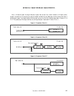
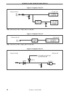
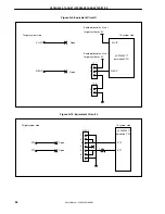
performance aspect. The target interface of this product can be any one of the interfaces described in Figures A-1 to
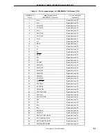
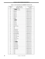
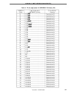
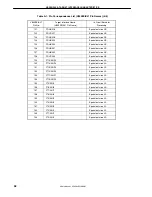
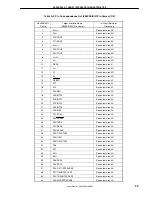
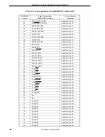
A-10. The processing of the target interface for each target device is described in Tables A-1 to A-3.
Figure A-1. Equivalent Circuit A
Figure A-2. Equivalent Circuit B
Figure A-3. Equivalent Circuit C
Numbered port
(other than P9)
µ
PD70F3217
emulation CPU
Port
pin
Target system side
IE system side
EP1K100FC484
(FPGA)
QS3384Q
(bus switch)
Alphabetic port
A
B
HD151015
(level shifter)
A
B
5 V
Same potential as BV
DD
1 M
Ω
Target system side
IE system side
EP1K100FC484
(FPGA)
P9
HD151015
(level shifter)
A
B
5 V
µ
PD70F3217
emulation CPU
P9
Same potential as BV
DD
Target system side
IE system side

