


-27-
Service Manual CP-785F
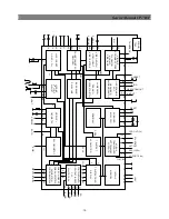
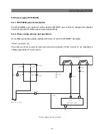
V
i(1),
V
i(2),
V
i(3)
1,2,3
R
i
Ra
3x
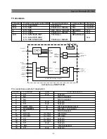
THERMAL
PROTECTION
CIRCUIT
VIP
REFERENCE
DIFFERENTIAL
STAGE
R
f
1x
3x3x
MIRROR 4
CASCODE 1
MIRROR 5
9,8,7
V
oc(3),
V
oc(2),
V
oc(1)
MIRROR 3
MIRROR 2
MIRROR 1
CASCODE 2
4
MGK278
o(m)
V
DD
6
1x
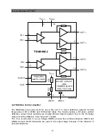
TDA6107Q
CURRENT
SOURCE
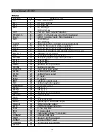
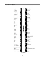
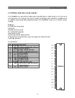
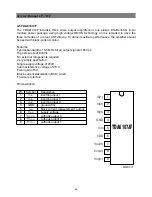
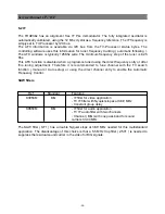
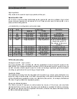
4-6 24C08 8 Kbit EEPROM
features :
8 Kbit serial I2C bus EEPROM
Single supply voltage : 4.5 V to 5.5 V
1 Million Erase/Write cycles (minimum)
40 year data retention (minimum)
Pin description
Pin No.
Name
Description
1,2,3
E0, E1, E2
Device address
5
SDA
Serial Data/Address Input/Output
6
SCL
Serial clock
7
WC
Write contro
8
Vcc
Supply voltage
4
Vss
Ground
The memory device is compatible with the I2C memory standard. This is a two wire serial
interface that
uses a bi-directionnal data bus and serial clock. The memory carries a built-in- 4-bit unique
device type
identifier code (1010) in accordance with the I2C bus definition.
Serial Clock (SCL)
The SCL input is used to strobe all data in and out of the memory.
Serial Data (SDA)
The SDA pin is bi-directionnal, and is used to transfer data in or out of the memory
Summary of Contents for DTE-29U1TH
Page 67: ...Service Manual CP 785F 66 7 Exploded view ...
Page 68: ...Service Manual CP 785F 67 8 PCB Layout 8 1 Main PCB ...
Page 69: ...Service Manual CP 785F 68 8 2 AV PCB ...
Page 70: ... 69 Service Manual CP 785F 9 Circuit Diagram ...
Page 71: ...NEC Corporation 7 1 SHIBA 5 CHOME MINATO KU TOKYO 108 8001 JAPAN ...