


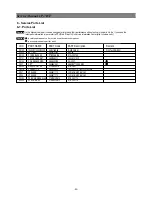
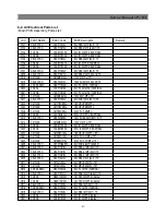
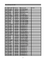
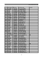

-42-
Service Manual CP-785F
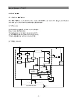
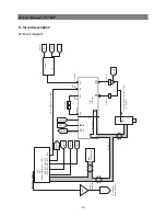
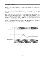
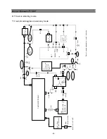
When the MOSFET is ON, the STR-F665X internal capacitor C1 is charged at the constant
voltage 6.5V.
At the same time, the voltage at pin 1 (OCP / FB) increases with the same waveform as the
MOSFET drain current.
When the pin 1 voltage reaches the threshold voltage V
TH1
= 0.73V, the STR-F665X internal
comparator 1 starts operating. The STR-F665X internal oscillator is inverted and the
MOSFET turns OFF.
When the MOSFET turns OFF, charging of STR-F665X internal capacitor C1 is released
and C1 starts discharging by the STR-F665X internal resistance R1. So, C1 voltage starts
falling in accordance with the gradient regulated by the constant discharging time of C1 and
R1. So, this means that the fixed time determined by C1 and R1 is the OFF-time of the
MOSFET.
When C1 voltage falls to around 3.7V, the STR-F665X internal oscillator is reversed again
and the MOSFET turns ON. C1 is quickly charged to around 6.5V
The MOSFET continues to oscillate by repeating the above procedure.
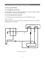
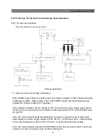
* STR-F665X protection circuits
overcurrent protection function (OCP)
Overcurrent protection is performed pulse by pulse detecting at STR-F665X pin 1 (OCP) the
peak of the
MOSFET drain current in every pulse.
latch circuit
This circuit sustains an output low from the STR-F665X internal oscillator and stops operation
of the power supply when overvoltage protection (OVP) and thermal shutdown (TSD) circuit are
under operation
thermal shutdown circuit (TSD)
This circuit triggers the latch circuit when the frame temperature of STR-F665X IC exceeds
140¡C
overvoltage protection circuit (OVP)
This circuit triggers the latch circuit when the V
in
voltage exceeds 22V (typ.)
Summary of Contents for DTE-29U1TH
Page 67: ...Service Manual CP 785F 66 7 Exploded view ...
Page 68: ...Service Manual CP 785F 67 8 PCB Layout 8 1 Main PCB ...
Page 69: ...Service Manual CP 785F 68 8 2 AV PCB ...
Page 70: ... 69 Service Manual CP 785F 9 Circuit Diagram ...
Page 71: ...NEC Corporation 7 1 SHIBA 5 CHOME MINATO KU TOKYO 108 8001 JAPAN ...