background image


System Preparation and Configuration


DS2000 Hardware Manual


Section 1: Installing the Cabinet


1-3


1


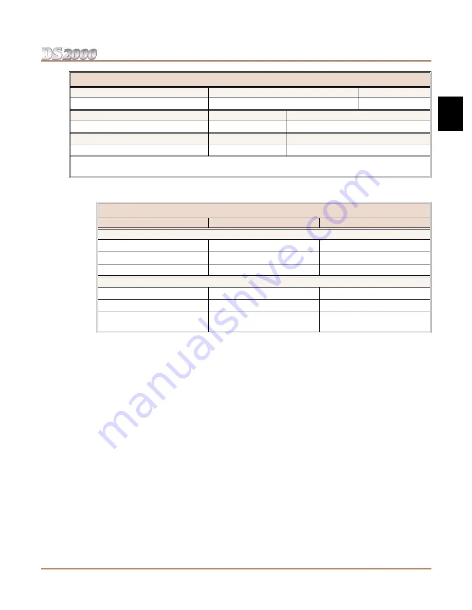
The following table shows the port capacity of each DS2000 PCB.

Since the Expanded Database maintains database records for all extensions and trunks, you have 
the option of using 


Program 9902 - Set Up Stations (DS2000)


and 


Program 9903 - Set Up 

Trunks (DS2000)


 to assign a station and a trunk PCB 


to the same slot


. When you plug in an ASTU 

or DSTU PCB into the slot, the ports on the PCB access the associated station numbers. If you 
remove that PCB and plug an ATRU in its place, the ports on the ATRU PCB access the associated 
trunk numbers. Refer to the 


Software Manual 


on the 


System Document CD


 that came with your sys-

tem for more.


Voice Mail Stations

Station Numbers

Extension Numbers


201-208

500-507


UCD Groups

Total Groups

UCD Group Master Extension Numbers


8

700-707


Ring Groups

Total Groups

Ring Group Master Extension Numbers


8

600-607


1


 Available for digital station port secondary station numbers. These are used for the second channels on 2-OPX 

Modules and Digital VANGARD Voice Mail.


DS2000 PCB Port Capacities


PCB

Description

Port Capacity

Station PCBs


16DSTU PCB

16 Digital Station PCB

16 (1-16)

4ASTU PCB

4 Analog Station PCB

4 (1-4)

8ASTU PCB

8 Analog Station PCB

8 (1-8)


Trunk PCBs


4ATRU PCB

4 Analog Trunk PCB

4 (1-4)

8ATRU PCB

8 Analog Trunk PCB

8 (1-8)

T1 PCB

T1/E1 PCB

24 (1-24) when enabled for T1
30 (1-30) when enabled for E1


Default Numbering in DS2000

Summary of Contents for DS2000 IntraMail

Page 1: ...he system This simplifies installation because you no longer have to use system programming to activate station and trunk PCBs after you plug them in See Automatic Slot Configuration on page 1 4 for m...

Page 2: ...ut notice and NEC America Inc has no obligation to provide any updates or corrections to this manual Further NEC America Inc also reserves the right without prior notice to make changes in equipment d...

Page 3: ...ing the Wall Mount Bracket 1 10 Mounting the Wall Mount Bracket 1 10 Hanging the Cabinet 1 11 Grounding the Cabinet 1 12 Removing the Right Side Panel 1 12 Attaching the Ground Wires 1 12 RFI Suppress...

Page 4: ...ay for External Paging Control 4 2 Programming the Relay for External Paging Control 4 2 Music Source 4 3 Installing a Music Source 4 3 Programming Background Music 4 3 Programming Music on Hold 4 3 P...

Page 5: ...ring Site Data from a PC Card 5 4 PC Card Restore Error Messages 5 4 Loading New System Software 5 5 Loading System Software from a PC Card 5 5 SMDR 5 6 Installing SMDR 5 6 Programming SMDR 5 6 Testin...

Page 6: ...Table of Contents iv Table of Contents DS2000 Hardware Manual...

Page 7: ...uding a test set a punch down tool and a digital voltmeter Before Installing Make sure you have a building plan showing the location of the common equipment extensions the telco demarcation and earth...

Page 8: ...ou don t have any ports installed to connect them You can t call station and trunk numbers directly you need the associated extension numbers to do that see below Extension Numbers Extension numbers a...

Page 9: ...ers Refer to the Software Manual on the System Document CD that came with your sys tem for more Voice Mail Stations Station Numbers Extension Numbers 201 208 500 507 UCD Groups Total Groups UCD Group...

Page 10: ...CBs in any slot in any order Automatic Slot Configura tion will properly handle the numbering Power up the system On power up the system scans the PCBs from left to right and sets up the extension and...

Page 11: ...STU PCBs under any circumstances The first 16DDSTU PCB you install must be in the first slot CN1 Maximum configuration is 64 ports The total of all extensions and trunks cannot exceed 64 Always use th...

Page 12: ...for each PCB DSS Console and 2 OPX Module installed in the Qty column The number of keysets and single line sets does not affect the System Load Factor 2 For each item for each Load Type multiply the...

Page 13: ...stalled the capacity is If you have two power supplies installed the capacity is If you have three power supplies installed the capacity is 5 VDC 40 5 VDC 80 5 VDC 120 40 VDC 48 40 VDC 80 40 VDC 120 N...

Page 14: ...s taking care to adhere to standard installation practices and local codes The equipment cabinet requires a three prong dedicated 110 VAC 60 Hz circuit NEMA 5 15 receptacle The AC receptacle must be w...

Page 15: ...of the cabinet cover 2 Lift up slightly on the front of the cover then gently slide the cover back to remove it Figure 1 2 8 Slot Cabinet Installation Layout Figure 1 3 Removing the Cover 80000 61 8...

Page 16: ...king material in the Main Equipment Cabinet box Unpack the wall mount bracket and mounting screws Mounting the Wall Mount Bracket Mount the wall mount bracket see Figure 1 5 Mounting the Wall Mount Br...

Page 17: ...l mount hanger as shown See Figure 1 6 Hanging the 4 Slot Cabinet below when hanging a 4 slot cabinet See Figure 1 7 Hanging the 8 Slot Cabinet below when hanging an 8 slot cabinet 2 Using the remaini...

Page 18: ...ight side panel down until it swings clear of the cabinet Attaching the Ground Wires The system provides two ground terminations Each ground connects from the system to the ground termina tion using 1...

Page 19: ...For earth ground Run a ground wire from the ETH lug to a known earth ground For PBX Ground Run a ground wire from the PBXG lug to the telco ground If your system will have a T1 Trunk PCB Run a 12 AWG...

Page 20: ...appropriate PCB as possible For Ground Wires You must install a separate RFI assembly for the ground wire s in all systems If your system has 2 ground wires install them both in the same assembly For...

Page 21: ...the power supply An 8 slot cabinet may require up to 3 power supplies using slots CN101 CN102 and CN103 Refer to System Configuration on page 1 4 for more Install the first supply in slot CN101 Instal...

Page 22: ...Power Supply Installation 1 16 Section 1 Installing the Cabinet DS2000 Hardware Manual...

Page 23: ...must plug into slot CN1 All other PCBs including 16DSTU PCBs can plug into slots CN2 CN8 Slots CN5 CN8 are only available with the 8 slot cabinet A 4 slot cabinet can only accept two 16DSTU PCBs In an...

Page 24: ...rnal paging output and associated relay Real Time Clock Battery for short term 14 day backup of the customer s site specific data Installing the CPU The CPU PCB installs in the CN0 slot in the Main Eq...

Page 25: ...DSTU PCB Figure 2 4 Figure 2 5 1 Plug the 16DSTU PCB for extensions 300 315 into slot CN1 2 Plug in additional 16DSTU PCBs as required See System Configuration on page 1 4 for more 3 Set the mode swit...

Page 26: ...Installing PCBs 2 4 Section 2 PCB Installation DS2000 Hardware Manual Figure 2 4 Digital Station 16DSTU PCB Figure 2 5 Installing the 16DSTU PCB Mode switch 80000 31 4 Slot Cabinet Shown...

Page 27: ...ects 4 analog extensions Refer to Section 3 Installing Extensions and Trunks for wiring instructions To install the ASTU PCB Figure 2 6 Figure 2 7 1 Plug in ASTU PCBs as required See System Configurat...

Page 28: ...g Extensions and Trunks for wiring instructions To install the ATRU PCB Figure 2 8 Figure 2 9 1 Plug in ATRU PCBs as required See System Configuration on page 1 4 for more 2 Set the mode switch on eac...

Page 29: ...10 Figure 2 11 1 Set jumpers CN7 and CN9 to the T1 position 2 Plug in T1 Trunk PCBs as required See System Configuration on page 1 4 for more 3 Set the mode switch on each T1 PCB to RUN 4 Using a sta...

Page 30: ...Installing PCBs 2 8 Section 2 PCB Installation DS2000 Hardware Manual Figure 2 11 Installing the T1 Trunk PCB 4 Slot Cabinet Shown 80000 76...

Page 31: ...ock and Installation Cable P N 80892 for optional equipment Punching Down the Cables The Installation Cables have six 8 pin jacks installed on one end and are unterminated on the other Each 8 pin jack...

Page 32: ...19 20 21 22 23 24 25 26 27 28 29 30 31 32 33 34 35 36 37 38 39 40 41 42 43 44 45 46 47 48 49 50 5 4 3 6 2 7 1 8 5 4 3 6 2 7 1 8 5 4 3 6 2 7 1 8 5 4 3 6 2 7 1 8 5 4 3 6 2 7 1 8 5 4 3 6 2 7 1 8 300 T 3...

Page 33: ...WHT WHT BRN BRN WHT WHT SLT SLT WHT RED BLU BLU RED RED ORN ORN RED RED GRN GRN RED RED BRN BRN RED RED SLT SLT RED BLK BLU BLU BLK BLK ORN ORN BLK BLK GRN GRN BLK BLK BRN BRN BLK BLK SLT SLT BLK YEL...

Page 34: ...Connecting Blocks 2 12 Section 2 PCB Installation DS2000 Hardware Manual Figure 2 14 Securing the Cables 80000 33...

Page 35: ...BRN 4T BRN WHT 4R 80000 18C 4T 3T 2T 1R 1T 2R 3R 4R 1 2 3 4 5 6 7 8 The following products should help if you make your own cables The connector is gener ally referred to as a RJ45 connector wired in...

Page 36: ...Connecting Blocks 2 14 Section 2 PCB Installation DS2000 Hardware Manual...

Page 37: ...within 6 feet of the telephone s location 3 For each extension run one pair 24 AWG station cable from the cross connect block to the modular jack 4 Terminate the station cable WHT BLU BLU WHT leads t...

Page 38: ...g Trunks on page 2 11 as a guide insert the mod jacks into the appropri ate connector on the PCB 2 For each trunk run one pair cross connect wire between the pins on the cross connect block and the CP...

Page 39: ...s the station and trunk cabling more accessible To power up the system Figure 3 3 through Figure 3 5 1 Make sure the system is properly grounded and the PCB bracket is reinstalled and secured 2 Instal...

Page 40: ...Power Up and System LEDs 3 4 Section 3 Installing Extensions and Trunks DS2000 Hardware Manual Figure 3 4 CPU Status LEDs Figure 3 5 DSTU ASTU and ATRU Status LEDs...

Page 41: ...shing the Installation Reinstalling the Side Panel To reinstall the side panel Figure 3 6 1 Carefully realign the right side panel and slide it into position 2 Reattach the two screws that secure the...

Page 42: ...the Front Cover To reinstall the front cover Figure 3 7 1 Hook the tabs on the rear of the cover into their associated slots 2 Push the front of the cover into place 3 Screw in the two captive screws...

Page 43: ...r crimping tool Hubbell BRFT4P Snap On 8 Position Modular Plug does not require a special crimping tool To connect an External Paging amplifier Figure 4 1 1 Find an available connector in a station ca...

Page 44: ...y cross connected 2 For the connector chosen locate pins 3T and 3R and connect the device the relays will control 3 Plug the modular jack into the CPU modular connector Programming the Relay for Exter...

Page 45: ...block is properly cross connected 2 For the connector chosen locate pins 2T and 2R and connect the music source 3 Plug the modular jack into the CPU modular connector Programming Background Music In...

Page 46: ...run one pair of 24 AWG station cable from the cross connect block to the telephone s modular jack 5 Terminate the station cable WHT BLU BLU WHT leads to the RED and GRN lugs in the modular jack 6 Inst...

Page 47: ...ate to both the DSS Console and telephone See Figure 4 5 Installing a 24 Button DSS Console below for more Programming DSS Consoles 1801 DSS Type For the extension to which you have connected the DSS...

Page 48: ...DSS Console 4 6 Section 4 Optional Equipment DS2000 Hardware Manual Figure 4 6 Installing a 110 Button DSS Console 80000 44B To 625 Modular Jack DSS Console Keyset...

Page 49: ...ay prevent you from using a connector on the trunk block for optional equipment 2 For the connector chosen cross connect the associated wire pair from the trunk or station block to the cross connect b...

Page 50: ...in programming To set up the 2 OPX Module secondary station In 9902 Set Up Stations DS2000 assign an unused station number e g 97 to the 2 OPX Module secondary station If you use station 97 the second...

Page 51: ...om the outside holes to the inside holes Do not tighten the screws 2 Attach the wall mount brackets to each side of 2 OPX Module and tighten the screws 3 With the connectors facing down mount the 2 OP...

Page 52: ...beneath the telephone s hookswitch Wall Mounting a Key Telephone To mount the telephone on the wall Figure 4 10 1 Using the screws provided attach the wall mount bracket to the wall in the desired loc...

Page 53: ...nt bracket and snap into place To remove the telephone from the wall mount bracket Figure 4 12 1 From the front of the phone grab the tabs that secure the telephone to the wall mount bracket 2 While p...

Page 54: ...one of two positions low and high To use the desk stand low position Figure 4 13 Flip up each telephone leg until it snaps into place To use the desk stand high position Figure 4 13 1 Flip up each te...

Page 55: ...telephone base 3 Separate the telephone faceplate from the telephone base 4 On the left side of the telephone base remove the plastic molding that covers the hole for the REJ con nector You only need...

Page 56: ...g the telephone line cord 2 While pressing HOLD plug the telephone back in All the LED elements in the display will fill 3 Release HOLD 4 Dial 1 to test the green LEDs in the keys 5 Dial 2 to test the...

Page 57: ...ramming mode ICM 372000 HOLD 4 Dial 9906 HOLD You see START To quit program 9906 instead dial N HOLD 5 DialY HOLD You see 9906 DATABASE NAME 6 Enter a name for the database you want to save up to 10 c...

Page 58: ...d Backup Error Messages PC Card Backup Error Messages This error message Means this NO PCCARD The PC card is not installed Install the PC card and try again ERASE FAILED The system could not overwrite...

Page 59: ...these keys to enter the character in the white cell 1 2 3 4 1 dash backslash apostrophe 1 2 A B C 2 3 D E F 3 4 G H I 4 5 J K L 5 6 M N O 6 7 P Q R S 7 8 T U V 8 9 W X Y Z 9 0 SPACE 0 To enter charac...

Page 60: ...t database stored If no data bases are stored you see 9907 DB00 empty 6 Press VOL or VOL to scroll through the data base addresses and select the one you want to restore There are 16 data base address...

Page 61: ...ally reload the factory installed default program entries 2 Insert the PC Card into the CPU see Figure 5 1 Using the PC Card on page 5 2 3 Be sure the CPU mode switch is set to BOOT 4 Press the reset...

Page 62: ...e adaptor into the DB9M COM connector on the back of your PC The communications parameters of the CPU serial port are 19200 8 N 1 19200 baud eight data bits no parity and 1 stop bit If you have a PC c...

Page 63: ...ay see some diagnostic data If you press Enter again you will see If you don t see anything or garbage on your screen check your connections and HyperTer minal settings and try again 7 From the PC or...

Page 64: ...nd of the adaptor into the DB25F connector on the back of your modem 4 Following the instructions that came with your modem connect a trunk and the modem s power supply To call from a PC at a remote s...

Page 65: ...Making Your Own Data Cables DS2000 Hardware Manual Section 5 Maintenance Options and SMDR 5 9 5 Making Your Own Data Cables Figure 5 6 Making Your Own Data Cables...

Page 66: ...ur System You may need to reset your system for troubleshooting purposes To reset your system Figure 5 7 1 Make sure the MODE switch is set to RUN 2 Following the illustration below press the red rese...

Page 67: ...CO PBX lines 4 Slot 64 8 Slot 64 Digital Telephones 4 Slot 32 8 Slot 96 Analog Telephones 4 Slot 24 8 Slot 56 DSS Consoles 1 max per keyset 4 max per system Power Failure Telephones 2 per ATRU PCB Ext...

Page 68: ...s where sulfuric gases are produced 3 In places where shocks or vibrations are frequent or strong 4 In places where water or other fluids come in contact with the main equipment 5 In areas near high f...

Page 69: ...ephone type and loop length Ringing voltage 50 70 VAC sine wave High Voltage Message Waiting 150 VDC Trunk Voltages Ringing voltage 42 103 VAC 20 Hz Battery from telco 44 56 VDC External Paging Output...

Page 70: ...PCB Input Impedance 10K Ohms Input Level 18 dBr 2 dBr 1 0 Khz FCC Registration Information Model DX7NA 112 48 DS2000 Manufacturer NEC Infrontia FCC Part 15 Registration Class A FCC Registration Number...

Page 71: ...cables must be run on the floor use cable protectors 3 Cable runs for key telephones single line telephones Door Boxes and 2 OPX Modules must be a dedicated isolated cable pair Device Cable Type Cabl...

Page 72: ...0555 Wall Mount Kit 80579 Analog Telephones customer provided Peripheral Station Equipment Description Part Number 2 OPX Module 92177A Common Equipment Description Part Number 4 Slot KSU 8 Slot KSU 80...

Page 73: ...to the Aspire Mail and Ultra Mail System Guide P N 17710SWG Replacement Parts Description Part Number Handset and Cord Assembly 80150 Noise Cancelling Handset 80150NC 22 Button Clear Plastic Cover 806...

Page 74: ...Parts List 6 8 Section 6 Specifications and Parts DS2000 Hardware Manual...

Page 75: ...ng 4 5 E Electrical Specifications 6 2 6 3 Environmental Requirements 6 2 Environmental Specifications 6 2 Error Messages 5 2 External Paging 4 1 6 3 External Paging Relay Control 4 2 External Paging...

Page 76: ...DS2000 Cover 1 9 Removing the DS2000 Right Side Panel 1 12 Resetting Your System 5 10 Restore Error Messages 5 4 Restoring Site Data from a PC Card 5 4 RFI Suppressor Assemblies for DS2000 1 14 S Sit...

Page 77: ...ec com Other Important Telephone Numbers Sales 203 926 5450 Customer Service 203 926 5444 Customer Service FAX 203 926 5454 Technical Service 203 925 8801 Discontinued Product Service 900 990 2541 Tec...

Page 78: ...80000INS09 80000INS09 July 28 2003 Printed in U S A NEC America Inc Corporate Networks Group 4 Forest Parkway Shelton CT 06484 TEL 203 926 5400 FAX 203 929 0535 cng nec com...

Reviews: