Making Connections 3-6
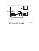
Figure 3-7: Connections Diagram
8.
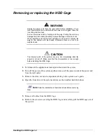
Install the side cover and components removed in 3 of the
Handling the HDD Cage
section. Refer to the system user’s guide for details.
IDE #3
PCI#1
IDE #2
IDE #1
PCI#2
PCI#3
PCI#4
PCI#5
CH1 CH2 CH3 CH4
Option
Option
Option
CD-ROM
5.25-inch
device bay
3.5-inch
disk bay
(Optional
hard disk
drives)
S-ATA RAID controller board
Floppy Disk
DAC LED connector
Master
Master
Master
Master
IDE cable
FDD cable
LED cable
I2C cable
Summary of Contents for 120Ef
Page 1: ... User s Guide HDD Cage ...
Page 2: ......
Page 4: ......
Page 6: ...iv ...
Page 17: ...System Overview 1 1 1 System Overview Identifying items Part Names and Functions ...
Page 20: ...System Overview 1 4 ...
Page 21: ...Handling the HDD Cage 2 1 2 Handling the HDD Cage ...
Page 24: ...Handling the HDD Cage 2 4 ...
Page 25: ...Making Connections 3 1 3 Making Connections ...
Page 31: ...Installing Hard Disk Drives 4 1 4 Installing Hard Disk Drives ...
Page 35: ...Appendix A 1 Appendix Operation Maintenance Specifications ...
Page 37: ... ...

