


System Overview 1-3
Part Names and Functions
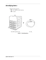
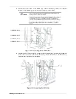
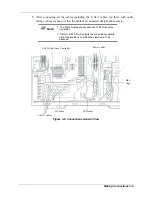
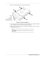
Figure 1-2: HDD Cage Part Names and Functions
1
Channel 1 (Port 1) S-ATA Connector
S-ATA Connector is to be connected to channel 1 on the S-ATA Disk
Array Controller.
2
Channel 2 (Port 2) S-ATA Connector
S-ATA Connector is to be connected to channel 2 on the S-ATA Disk
Array Controller.
3
Channel 3 (Port 3) S-ATA Connector
S-ATA Connector is to be connected to channel 3 on the S-ATA Disk
Array Controller.
4
Channel 4 (Port 4) S-ATA Connector
S-ATA Connector is to be connected to channel 4 on the S-ATA Disk
Array Controller.
5
I2C Connector
I2C Connector to be connected to the I2C cable.
6
Power Connectors
Power Connectors to which the Base Unit 5VDC and 12VDC power
cords are to be connected.
7
LED Connector Pins (2)
Connector pins control the Disk Access lamp (green) inside the Base
Unit.
1
2
3
4
5
6
7
Summary of Contents for 120Ef
Page 1: ... User s Guide HDD Cage ...
Page 2: ......
Page 4: ......
Page 6: ...iv ...
Page 17: ...System Overview 1 1 1 System Overview Identifying items Part Names and Functions ...
Page 20: ...System Overview 1 4 ...
Page 21: ...Handling the HDD Cage 2 1 2 Handling the HDD Cage ...
Page 24: ...Handling the HDD Cage 2 4 ...
Page 25: ...Making Connections 3 1 3 Making Connections ...
Page 31: ...Installing Hard Disk Drives 4 1 4 Installing Hard Disk Drives ...
Page 35: ...Appendix A 1 Appendix Operation Maintenance Specifications ...
Page 37: ... ...


