Product Manual | NU-350-USB2PTZ-B
Page 6 |
Hardware Anatomy
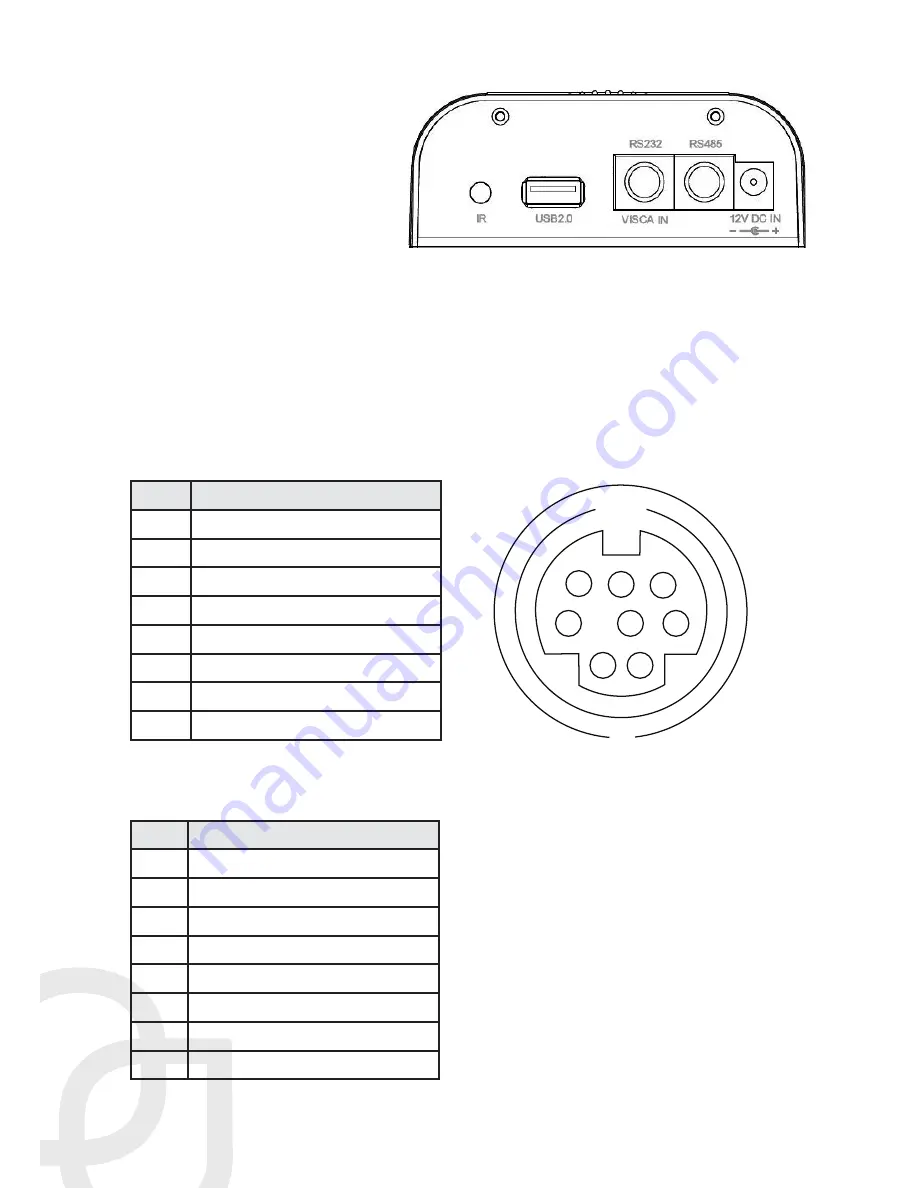
Camera Anatomy
IR receiver
USB 2.0 input
VISCA, RS-232C, RS-485 input
RS-485 output
DC12V 1.2A power input socket
VISCA to RS-232C IN Connector Anatomy
To control the camera via RS-232 or RS-485, match the controlling pins to the pins on
the provided VISCA cable.
RS-232 IN Pinout Chart
Use VISCA protocol @ 9600 baud.
Pin # Function
1
DTR In
2
DSR In
3
TXD In
4
GND
5
RXD In
6
GND
7
IR Commander Signal Output
8
N/A
RS-485 OUT Pinout Chart
Use PELCO-D protocol @ 38400 baud.
Pin # Function
1
Data Transmission Ready Out
2
Data Set Ready Out
3
Transmit Data Out
4
Ground
5
Receive Data In
6
Ground
7
RS-485 -
8
RS-485 +
1
2
3
4
5
6
7
8


