background image

22

Cirrus LT Plus User Manual v1.2 - Chapter 2

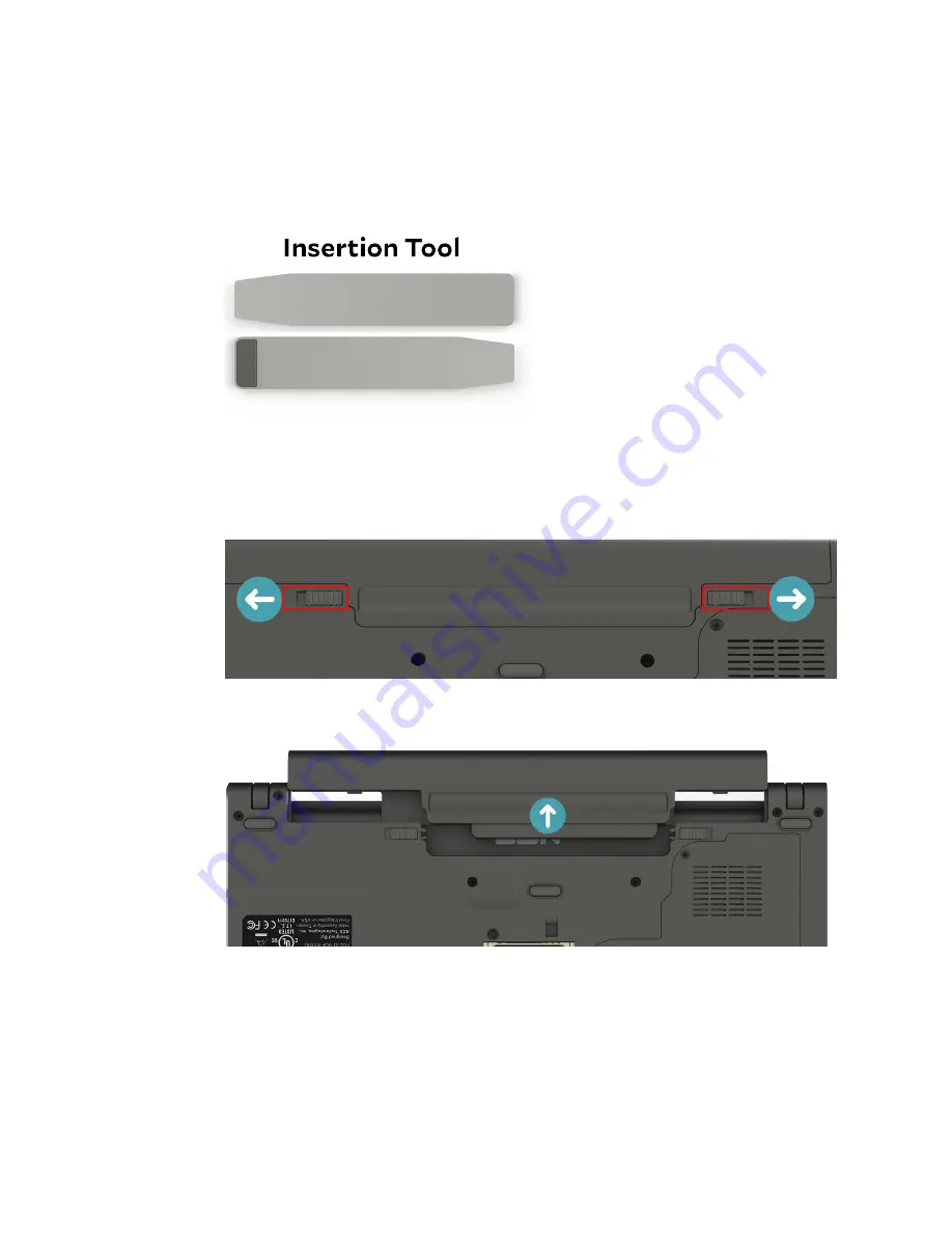
Removing the SIM card

To remove your SIM card from the Cirrus LT Plus, follow the steps below:

1. 

Make sure you have the insertion tool included with your Cirrus LT Plus 
packaging.

2. 

Remove the Cirrus LT Plus’ external battery from the notebook bottom by 
sliding the tabs to the unlocked position.

3. 

Remove the battery.

Summary of Contents for Cirrus LT Plus

Page 1: ...Computing Innovations TZ 251G v1 2 May 16 2016 Cirrus LT Plus User Guide ...

Page 2: ...upport 18 Installing Removing the SIM card 19 Installing the SIM card 19 Removing the SIM card 22 Starting your notebook 26 Opening the display panel 26 Turning on your notebook 27 Using the keyboard 27 Function keys 27 Touchpad 28 Point 28 Click 28 Double click 28 Drag 28 Using the fingerprint reader 29 Chapter 3 Making connections 30 Connecting external display devices 30 Connecting a projector ...

Page 3: ...88 Setting the duration of the OnScreen Menu OSM Timeout 89 How the Cirrus LT Plus power management modes are all related 91 Low power mode 95 Timing preferences 99 Device Manager 102 Speakers 102 On Lid Close 102 Touchpad Keyboard settings 104 Webcam 107 Administrator 108 Admin login 108 Administrator settings 109 Allow saving WiFi pwassword 109 Allow web portal 110 Change admin credentials 110 C...

Page 4: ...iguring advanced WiFi roaming 138 Enabling disabling Enhanced Roaming via the OSM Main Menu 138 Enabling Enhanced Roaming 138 Disabling Enhanced Roaming 140 Checking WiFi channels that are being scanned used via the OSM Main Menu 142 Configuring Enhanced Roaming via the Management Console MC 143 Chapter 11 Troubleshooting 150 General troubleshooting tips 150 Conflicts between Teradici and NCS Firm...

Page 5: ...5 Cirrus LT Plus User Manual v1 2 Icon Glossary 2 ...

Page 6: ... fields DO NOT use or store your notebook in extreme temperatures DO NOT place your notebook near fire or other sources of heat DO NOT expose to dust or corrosive materials DO NOT spray water or any other cleaning fluids directly on the display panel DO NOT expose your notebook to rain or moisture DO NOT tamper with the battery Keep this away from children DO NOT slam your notebook shut and never ...

Page 7: ...structions Do not dispose of battery in a fire It may explode Check with local authorities for disposal instructions Keep away from children Store unused battery in a normal room temperature range To optimize battery life make sure to let the battery drain before plugging it in to charge Leaving the notebook constantly plugged in will result in a deteriorating battery life This product is intended...

Page 8: ... a zero client Remote users have effortless access to a fully functional even HD computing ex perience and now secure computing functionality is available for the first time on a zero client laptop Compact lightweight and engineered for high performance Cirrus LT Plus using PCoIP technology is optimized for VMWare Horizon View for a highly efficient IT administrative experience and low cost of own...

Page 9: ...rrus LT Plus User Manual v1 2 Chapter 1 Chapter 1 Before you start Package contents Cirrus LT Plus notebook Lithium ion battery 65 Watt power adapter Cirrus LT Plus Quick Start Guide SIM card insertion tool ...

Page 10: ...1 2 9 3 4 6 7 3 5 8 10 1 Optional built in PC webcam 2 LCD screen 3 Speakers 4 Power button LED 5 Keyboard 6 Function Fn key 7 Touchpad buttons 8 LED indicators 9 Optional fingerprint reader 10 Smart card reader CAC or optional internal proximity card reader ...

Page 11: ... keyboard USB port 4 Dedicated mouse USB port Left view 6 2 3 4 5 6 1 1 Security key lock 2 DC in jack 3 Mini DisplayPort 4 Charging USB port 5 RJ 45 LAN jack 6 PCoIP USB ports This port is labeled Local on the notebook but it functions as a USB charging port for certain devices Devices plugged into this port will not be seen in the remote session ...

Page 12: ...iew Battery Docking station connector The docking station port may be covered with a rubber cover to keep dust and debris out of the connector when not in the dock Notebook LEDs 2 3 4 6 1 5 1 Battery 2 WiFi 3 PCoIP 4 Caps Lock 5 Num Lock 6 Proximity card ...

Page 13: ...2 Charging USB port 3 RJ 45 LAN jack 4 DVI 1 port 5 DVI 2 port 6 PCoIP USB 2 0 ports 7 Dedicated mouse USB port 8 Dedicated keyboard USB port 9 Speaker line out 10 Microphone 11 DC in jack Docking station LEDs 2 3 1 4 5 6 1 CapsLock 2 Battery 3 PCoIP Session Status 4 NumLock 5 WiFi Status LED 6 Power Connect Button ...

Page 14: ...ttery LED Green LED Battery is full or AC adapter is plugged IN Blinking Green LED Battery is charging Blinking Amber LED Low Battery Battery is under 10 charge or battery is not present Amber LED charging error NO LED normal operation battery discharging Wireless LED Green LED Wireless is enabled this can be on when not connected to a wireless LAN NO LED Wireless is disabled PCoIP LED Green LED C...

Page 15: ... notebook Using the keyboard Using the touchpad Navigating the OnScreen Menu OSM Powering up your notebook Your notebook can be powered up using the AC adapter a removable lithium ion battery or an optional factory installed dual battery configuration Connecting the AC adapter The AC adapter powers up your notebook and charges the battery Connect the AC adapter to the DC in jack of your notebook C...

Page 16: ...steps below 1 Align and slide the battery into the battery compartment 2 Push the battery into the compartment until the battery locks into place and make sure the latches are locked into position The left latch will automatically go into the locked position when you push the battery in place but you must manually lock the right latch as shown ...

Page 17: ...en the charging time to two hours If the Cirrus LT Plus is on it will take approximately eight hours to charge the unit Using battery power Install the charged battery in the battery compartment by removing the AC adapter if plugged in Your notebook will automatically use the battery power Recalibrating the battery If you notice your removable battery pack is not lasting as long over time you may ...

Page 18: ...the customer Install the removable battery as indicated above Charging both the removable and internal batteries while the Cirrus LT Plus is powered off will shorten the charging time to two hours If the Cirrus LT Plus is on it will take approximately five hours to charge the unit If your Cirrus LT Plus is equipped with dual batteries the external battery can be changed without powering down since...

Page 19: ...nu refer to Chapter 4 Installing the SIM card To install the SIM card into your Cirrus LT Plus follow the steps below 1 Make sure you have your SIM card and the insertion tool included with your Cirrus LT Plus on hand 2 Remove the Cirrus LT Plus external battery from the notebook bottom by sliding the tabs to the unlocked position 3 Remove the battery ...

Page 20: ...apter 2 4 Locate the SIM card slot located inside the notebook battery compartment as highlighted below 5 Using your fingers carefully line the SIM card with the chip side facing up and the clipped corner facing away from you with the slot ...

Page 21: ...rrus LT Plus User Manual v1 2 Chapter 2 6 Use the insertion tool to gently push the SIM card into the slot until you hear it click into place 7 Reinstall the external battery 8 Slide tabs to locked position ...

Page 22: ...our SIM card from the Cirrus LT Plus follow the steps below 1 Make sure you have the insertion tool included with your Cirrus LT Plus packaging 2 Remove the Cirrus LT Plus external battery from the notebook bottom by sliding the tabs to the unlocked position 3 Remove the battery ...

Page 23: ...23 Cirrus LT Plus User Manual v1 2 Chapter 2 4 Find the SIM card slot located inside the notebook battery compartment 5 Use the included removal tool to push to eject the SIM card ...

Page 24: ...24 Cirrus LT Plus User Manual v1 2 Chapter 2 6 Now use the opposite end of included removal tool with the black rubber pad tip as shown below to grip the SIM card and fully remove it from its enclo sure ...

Page 25: ...25 Cirrus LT Plus User Manual v1 2 Chapter 2 7 Reinstall the external battery 8 Slide tabs to locked position ...

Page 26: ...ting your notebook Opening the display panel The notebook lid is secured with small magnets while closed and is easily opened To open simply lift the cover lid up to the upright position To close carefully place the cover lid down Do not slam it shut ...

Page 27: ...ir actions Fn F1 Turns WiFi on and off Fn F2 Decreases screen brightness Fn F3 Increases screen brightness Fn F4 Turns Native Display on and off Fn F5 Toggles between various available display modes Fn F6 Enables and disables the touchpad Fn F7 Turns sound on and off Fn F8 Decreases volume Fn F9 Increases volume Fn F10 Brings up OnScreen Menu OSM Fn F11 Turns status bar on and off Fn F12 Enables o...

Page 28: ... cursor movements while typing Refer to Chapter 4 s Device Manager section to enable this feature To right click move the cursor to the item or object on the screen then press the right button Double click To double click move the cursor to the item or object on the screen then tap the touchpad twice or press the left button twice by default this tapping feature is disabled in NCS Firmware to prev...

Page 29: ...ng fingerprint reader There is also an option for a swipe fingerprint reader or for no fingerprint reader at all You will need to load your appropriate drivers on your virtual machine or remote host to support this device Drivers can be downloaded from our NCS website at http www ncst com content downloads 0 ...

Page 30: ...l video signals The DisplayPort cable is not included in the package It is sold separately or it may come with your external display device The Cirrus LT Plus is designed to support both passive and active mini DP to DVI adapters The Cirrus LT Plus is compatible with most new adapters but there are a few older adapters that will not work NCS sells a variety of adapters for most modern LCDs out in ...

Page 31: ...ves and hard drives that do not have their own power sources are not officially support ed Most of these devices tend to draw too much power from the USB port You can still connect these devices to the Cirrus LT Plus If the device only has one USB port use one of the two PCoIP USB ports on the left side of the notebook If the device has two USB ports one for enumeration and one for auxiliary power...

Page 32: ...enu Certain special multifunction or Bluetooth combo mouse and keyboards will work in the dedicated keyboard port Not all of these special devices have been tested As a general rule you can try different keyboards without harming the Cirrus LT Plus Special keyboards should be plugged into the dedicated USB keyboard port on the right hand side for compatibility Combo Bluetooth keyboard and mouse do...

Page 33: ... headphone as well as CTIA and OMTP Head sets Headsets are not compatible with the headphone port on the docking station or with the microphone jacks on the notebook or the docking sta tion Audio subsystem By default audio will be output to the Cirrus LT Plus built in speakers when the headphones headset port is not used If a webcam is installed the webcam microphone can be used for applications l...

Page 34: ...gging the audio jack of the microphone to the microphone jack of your notebook If you want to use the docking station microphone jack while on a virtual machine you must install a driver You can download this driver at http www ncst com content downloads 0 If you have a USB headphone and microphone device plug these into the PCoIP USB ports ...

Page 35: ...features two DVI D ports and a Fiber SFP port The notebook and docking station use different AC adapters You must connect the 90 Watt AC Adapter 19V 4 74A to the docking station in order for the Cirrus LT Plus to function correctly while in the docking station Connecting the docking station To connect your notebook to the docking station 1 Pull out the extender on the right side of the docking sta...

Page 36: ... notebook docking station port cover highlighted below is removed before you try to dock the notebook onto the docking station There is also a handy storage location for this port cover located on the docking station lever See the highlighted area shown below ...

Page 37: ...following highlighted guides below on both the notebook and the docking station for correct placement when connecting the notebook to the docking station There are two small triangle guides on the notebook lid There are also two guides on the docking station ...

Page 38: ...8 Cirrus LT Plus User Manual v1 2 Chapter 3 4 Line these up and then firmly press down on the lid of the notebook You should hear a click and then the notebook is properly docked into the docking station ...

Page 39: ... the docking station 1 Pull up the black lever on the top right side of the docking station If the black lever won t lift up you will need to unlock the docking station with the included keys shown below to remove the notebook The release lever will not lift up if locked 2 Lift the notebook out of the docking station ...

Page 40: ...ng ports of the docking station remain active highlighted below while docked These ports are labeled with an icon of a mouse and a keyboard However the two PCoIP and charging ports on the notebook will still work giving you a total of 6 working USB Ports when using the docking station and two charging USB ports Hotdocking Hot docking placing the Cirrus LT Plus on the docking station while the Cirr...

Page 41: ...the audio for remote hosts Connecting to the Teradici host PC Headset port or built in speaker configuration 1 Open the Control Panel Sound Playback tab 2 In the Playback tab select Headphones 3 High Definition Audio Device as the Default Communication Device ...

Page 42: ...ut port 1 Open the Control Panel Sound Playback tab 2 In the Playback tab select Headphones 3 High Definition Audio Device as the Default Device Connecting to VMHost 1 Download and install the latest PCoIP Audio Driver provided by Teradici PCoIP_ComponentInstaller exe ...

Page 43: ...anual v1 2 Chapter 3 2 Open the Control Panel Sound Playback tab 3 Ensure that the Teradici Virtual Audio Driver is selected as the default driver The Speakers setting will work for both the Headset Port and Dock Line out Port ...

Page 44: ... of the audio plugs while docked are as follows By default audio will be output to the built in speakers when Headset Line out port is not used If a webcam is installed the webcam mic can be used for applica tions like Skype When the line out port on the docking station is connected to an external speak er this port will get priority and internal speakers will not produce sound Simi larly docking ...

Page 45: ...o use fiber optic cable for more secure networking You will need to pull the tab lever out prior to installation as shown below To install the SFP module 1 Place the SFP module into the Fiber SFP port refer to Chapter 1 rear view port 1 for exact location Make sure the side with the green tab is facing up and the tab lever is pulled out as shown below ...

Page 46: ... User Manual v1 2 Chapter 3 2 Push the module all the way into the port 3 You will know the module is securely installed when you hear a click as you push it into place Pull the lever down back into place as shown below ...

Page 47: ...e OSM for your convenience OnScreen Menu OSM structure The OnScreen Menu OSM is based on a tree structure moving from left to right as you drill deeper into the menu system Each level of the tree will have a title and various options to choose from either click an option to move down the tree or to make a selection with the mouse pointer You can also click any option higher in the tree structure t...

Page 48: ...ring OSM Low Power Mode and Sleep Timing Preferences Device Manager For configuring speaker volume webcam and touchpad settings Administrator For configuring authentication credentials of local and administrator accounts and other administrator settings The bottom left of the main menu highlighted above also allows you to close the menu shut down the system restart the system and connect disconnec...

Page 49: ...wired and wireless settings and allows you to enable and disable both Ethernet and WiFi connections Ethernet To enable the Ethernet 1 Click the Network submenu 2 Select Ethernet 3 Click the Enable Ethernet selection box A green check mark signifies that Ethernet has been enabled as shown below ...

Page 50: ... Ethernet has been disabled WiFi All wireless configuration is done in these menus You can enable or disable wireless entirely If you want to auto connect to the same set of wireless LANs WLANs you can save those for auto connection at a later time this can also be disabled in the Administrator menu Once connected to a WLAN you can see signal strength and the IP Address obtained ...

Page 51: ...51 Cirrus LT Plus User Manual v1 2 Chapter 4 Disconnected This tells you if WiFi is connected or disconnected ...

Page 52: ...he Enable WiFi selection box A green check mark signifies that WiFi has been enabled To disable wireless 1 Click the Network submenu 2 Select WiFi 3 Click the Enable WiFi selection box A gray X signifies that WiFi has been disabled If both a wired and a wireless network are present wired will take priority based on its better performance over WiFi ...

Page 53: ...the Save Connection check box if you would like to save this information for future convenience you can disable this fea ture in the Administrator Menu Available wireless networks are sorted by signal strength WLANs that have higher signal strength are at the top of the list while low signal strength WLANs can be found at the bottom of the list To see Available Networks 1 Click the Network submenu...

Page 54: ...apter 4 4 Choose the network you wish to connect to Networks that do not broadcast their SSID will be placed at the bottom of the list and labeled as Join Other Network You will then have to provide the SSID password and security protocol ...

Page 55: ...work from the available networks list the OSM will automatically detect the proper network type You only need to select the network type of hidden networks When making wireless connections the Cirrus LT Plus only supports WPA2 and higher levels of security This system does not support WEP due to its many security flaws ...

Page 56: ...ngth is 64 characters IMPORTANT you cannot use certain characters in the wireless network name SSID and you cannot use certain characters in your password See below for a list of supported and unusable characters Supported SSID Characters letters numbers space symbols including _ Symbols printed on the English keyboard that are not supported in SSID are ...

Page 57: ...e Unicode and non english letters haven t been tested and will probably not be supported Preferred Networks Your preferred wireless networks are shown in this list You can remove or con nect to one of these networks by clicking on the chosen network and then either clicking Remove or Connect To see your preferred networks 1 Click the Network submenu 2 Select WiFi 3 Click Preferred Networks ...

Page 58: ...iFi Password in the System Admin Section This will add a new check box when signing onto WiFi networks labeled Save By checking this check box you will be adding this WiFi network as a preferred network If you would also like to auto connect to that network you must select the auto connect check box in the WiFi Networking Menu ...

Page 59: ...ct WiFi 3 Click Preferred Networks 4 Use the mouse cursor shown below to select the Network you wish to move up or down the list Once you click on the Network the selected row will be highlighted in grey Click the Up or Down button the num ber of times it will take to move the highlighted server to the desired position on the list 5 In the example below NETGEAR90 now in 3rd position is to be moved...

Page 60: ...2 Chapter 4 6 Note that NETGEAR90 is now in 1st position You can select other Networks to be moved up or down the list as needed 7 Once you are done prioritizing your preferred networks click the Com mit button to finalize the changes ...

Page 61: ...that an automatic connection has been enabled Enhanced Roaming To enable Enhanced Roaming 1 Click the Network submenu 2 Select WiFi 3 Click the Enable Enhanced Roaming selection box A green check mark signifies that WiFi has been enabled To disable Enhanced Roaming 1 Click the Network submenu 2 Select WiFi 3 Click the Enable Enhanced Roaming selection box A gray X signifies that WiFi has been disa...

Page 62: ... via 4G a SIM card must be installed into the notebook Refer to Chapter 2 for more information on how to install a SIM card Enabling and disabling 4G To enable 4G 1 Click the Network submenu 2 Select 4G 3 Click the Enable 4G selection box A green check mark signifies that 4G has been enabled ...

Page 63: ...63 Cirrus LT Plus User Manual v1 2 Chapter 4 To disable 4G 1 Click the Network submenu 2 Select 4G 3 Click the Enable 4G selection box A gray X signifies that 4G has been turned off as shown below ...

Page 64: ...It is im portant to note that while in VPN MODE the Cirrus LT Plus will be only able to make remote connections via VPN Normal connections that do not require a VPN will not be possible To connect again to remote connections that do not require VPN e g when you are at your corporate office you will need to DISABLE this feature Cirrus LT Plus currently only supports Cisco and Juniper VPN connection...

Page 65: ...N 3 Click the Enable VPN selection box 4 An alert shown below will then appear It states that while Enable VPN is active the Cirrus LT Plus can only make remote connections via VPN Normal connections that don t need VPN e g when you are at your corporate office won t be possible To allow remote connec tions that don t require VPN turn off Enable VPN mode ...

Page 66: ... that VPN has been enabled 6 Once Enable VPN is turned on the Network SSL VPN submenu will look like this Disabling SSL VPN To disable SSL VPN 1 Click the Network submenu 2 Select SSL VPN 3 Click the Enable VPN selection box A gray X signifies that VPN has been turned off as shown below ...

Page 67: ...o connect to a VPN Server type in its URL or IP Address in the Server URL field as shown below then click the Connect button For conve nience once a VPN server address is entered it will remain in this field until changed Only one VPN server can be stored at this time ...

Page 68: ... VPN server for any stored realms or groups Clicking on Realm Group will take you to another screen shown below that lists the reported realms groups on the VPN server Select your realm group as per instructions from your system administrator If you don t see the cor rect realm group on the list click the Refresh button ...

Page 69: ...mber of 2nd fac tor authentication methods If you are using any of the following 2nd factor authentication methods the Cirrus LT Plus will ask you additional questions after you initially submit your logon credentials Currently supported 2nd factor authentication methods include DuoSecurity https www duosecurity com Entrust Grid Cards with Juniper VPN only http www entrust com gridcard CAC Cards ...

Page 70: ...al v1 2 Chapter 4 Enabling and Disabling Use CAC If you are required to use your CAC card to make your VPN connection you need to enable this feature Enabling Use CAC To enable Use CAC 1 Click the Network submenu 2 Select Use CAC ...

Page 71: ...4 3 Click the Use CAC selection box A green check mark signifies that Use CAC has been enabled 4 When Use CAC is enabled the highlighted portion shown below of the Network SSL VPN submenu will display additional fields named Certificate and Pin ...

Page 72: ...h certificate to use you can ask your sys tem administrator To view a list of certificates to choose from click on Cert as shown below 2 Once you click on Cert it will take you to another screen shown be low that lists the available certificates for you on the CAC card Select the Certificate as per instructions from your system administrator If you don t see the correct Certificate on the list cli...

Page 73: ...eled Pin as shown below Disabling Use CAC To disable Use CAC 1 Click the Network submenu 2 Select SSL VPN 3 Click the Use CAC selection box A gray X signifies that Use CAC has been turned off as shown below 4 When Use CAC is disabled the highlighted portion shown below of the Network SSL VPN submenu will display fields named User Name Password and Remember username ...

Page 74: ...is where you will enter your logon credentials These fields can change depending on your connection method For example if you are using CAC you will be asked for a PIN instead If you would like the GUI to retain your username for convenience check the Remember username to enable this feature ...

Page 75: ...date a server certificate enable this feature Connect Status Buttons Once you are done configuring the SSL VPN setup click the Connect button to connect to your VPN Server Clicking the Status button gives you more information about your current VPN connection which may be useful for troubleshooting and or admins ...

Page 76: ...o pop up for you to interact with that WiFi net work s web interface To connect to a Public WiFi Open Network you are often presented with a web page to accept a usage agreement like the example shown below In these cases Cirrus LT Plus supports most of these types of authentica tion web pages The Cirrus LT Plus Network Settings are set to Web Portal by default If for added security you want to di...

Page 77: ...nd you should be able to do a remote session You may need to click REFRESH on the Web Portal to display the web page If for added security you want to disable this feature you can in the Admin istrator submenu described later in Chapter 4 under the Administrator section NCS strives to support many different types of web portal pages but unfortu nately incompatibilities will arise In these cases pl...

Page 78: ...apter 4 Display Settings In the Display Settings Menu you can select the display configuration of the notebook and adjust display brightness You may want to disable the native LCD if you are using a docking station or miniDP port for video ...

Page 79: ...e Display 1 Click the Display Settings submenu 2 Click the box next to Native Display On The Native Display will then turn off You can also toggle the Native Display on and off by pressing Fn F4 To turn on the Native Display 1 To turn on the Native Display select the green check mark as shown be low Fn F4 will also toggle the display on off ...

Page 80: ...esired screen brightness Moving the slide to the right will increase the bright ness and moving the slide to the left will decrease the brightness Al ternatively you can decrease screen brightness by pressing Fn F2 or in crease it by pressing Fn F3 Lowering the screen brightness can save battery life Status Bar The status bar submenu allows you to control the visibility and position of the status ...

Page 81: ... status bar visibility 1 Click the Status Bar submenu 2 Under the Status Bar Visible section choose On or Off To change the status bar position 1 Click the Status Bar submenu 2 Under the Status Bar Position section choose Upper Left Upper Center or Upper Right ...

Page 82: ...ng display configurations you can select 1 Use Native LCD Display Only 2 Clone Native LCD on Display 1 of docking station 3 Turn off Native LCD Use Display 1 of docking station and Display 2 of the Mini DP port or docking station 4 Use Display 1 on docking station only 5 Use LCD and Display2 of the Mini DP port or docking station The OSM will only appear on the native display and displays connecte...

Page 83: ... on Display 1 of docking station 1 In order to Clone your display with a docking station you will need to connect your laptop into the docking station and then connect an exter nal display to PCoIP1 Local DVI1 Port You then select the following option in the OnScreen Menu as shown below 2 This cloning method will duplicate the same display resolution of the Cirrus LT Plus LCD and is locked to this...

Page 84: ...P port or docking station This option allows you to close the notebook lid and use Display 2 or have one display plugged into the docking station and a second mini DP Port for another screen for an extended desktop Option 4 Use Display 1 on docking station Only Choose this option if you wish to use Display 1 on the docking station only ...

Page 85: ...sion If you are not using a dock ing station you may also use this mode to clone your display and to make mini DP the primary display by following the steps below Cloning displays without a docking station 1 In order to clone two displays without the use of a docking station you must first attach a display to the mini DP port on the notebook In the OSM Menu navigate to Display Settings and select ...

Page 86: ...Display Cloning 4 Next Click Apply and then OK How to make mini DP the Primary Display without docking sta tion 1 In order to make the mini DP the primary display without the use of a docking station you must first attach a display to the mini DP port on the notebook In the OSM Menu navigate to Display Settings and select the following option as shown below ...

Page 87: ...v1 2 Chapter 4 2 Access the Teradici Firmware Configuration Menu and click Options User Settings 3 Navigate to the Display Topology tab Check the Primary Port 2 4 Click Apply and then OK to close the Teradici Firmware as shown below ...

Page 88: ...l v1 2 Chapter 4 Power Management The Power Management Section allows you to customize the Cirrus LT Plus On Screen Menu OSM Timeout determine when Low Power Mode should be en abled and to choose when Sleep Mode should be enabled ...

Page 89: ...are Menu Via the OSM Power Management Power Settings OSM Timeout To change the timeout duration via the OnScreen Menu Timeout 1 Click the Power Management submenu and then click the OSM Timeout bar as shown below 2 The Menu Display Time Out Section will appear as shown below You may choose between Do Not Sleep 1 Minute 5 Minutes 15 Minutes 30 Minutes or 60 Minutes 5 Minutes is the default setting ...

Page 90: ... Power Tab 3 Enter the new duration of the OSM Screen Saver Timeout in seconds not minutes For example if you wanted to set the duration to 10 minutes you would enter 600 seconds Teradici s Firmware OSM Screen Saver Timeout default is set to 300 seconds or 5 minutes If you enter 0 Sec onds the OSM Screen Saver Timeout will only be disabled in the Teradi ci Firmware 4 Click the Apply button when yo...

Page 91: ...Cirrus LT Plus will automatically use the lowest selected interval 2 Next if the Low Power modes are enabled the Sleep mode will activate after the duration specified 3 Auto Power Off is the lowest setting available When Auto Power Off is configured the machine will shut off completely after the duration of this setting has elapsed However this duration doesn t start until after the machine has en...

Page 92: ...ere is no mouse or keyboard activity for a duration greater than X the LCD will turn off 2 If the Teradici OSM Screen Saver Timeout Menu is set to X seconds and there is no mouse or keyboard activity for a duration greater than X sec onds the LCD will turn off More about the OnScreen Menu s Do Not Sleep option If Do Not Sleep is enabled AND the Teradici OSD Timeout Menu is enabled Setting the OnSc...

Page 93: ...the other Power Management features Sleep Mode Timeout and Auto Power Off will not change If Do Not Sleep is enabled AND the Teradici OSD Timeout Menu is disabled If for some reason both the OnScreen Menu Timeout AND the Teradici OSD Timeout values are disabled as shown below this will disable all Cirrus LT Plus Power Management features including Sleep Mode Timeout and Auto Power Off even if they...

Page 94: ...e when OSM s Do Not Sleep is enabled AND the Teradici OSD Timeout Menu is turned off all of Cirrus LT Plus Power Management features will be disabled and the Cirrus LT Plus may not run optimally En suring that the OnScreen Menu Timeout AND the Teradici OSD Timeout value are both enabled will save energy and automatically turn off the LCD when it is supposed to ...

Page 95: ...Mode and Auto Power Off will turn off and the unit will not enter sleep mode To turn on Low Power Mode 1 Click the Power Management submenu 2 Click the box next to Low Power Mode When the green check mark is selected Low Power Mode will then be enabled To turn off Low Power Mode 1 Click the Power Management submenu 2 Click the box next to Low Power Mode When the gray x is selected Low Power Mode w...

Page 96: ...de 1 Click the Power Management submenu 2 Click the box next to Enable In Session When the green check mark is selected Enable In Session Mode will then be turned on If Enabling In Session and Low Power Mode are both turned on 1 When Enable In Session and Low Power Mode are enabled simultaneous ly as shown below the low power modes Sleep Mode and Auto Power Off will work even while connected to a ...

Page 97: ...cted En able In Session Mode will be turned off Enabling Plugged In Mode With this mode enabled the unit will go to sleep in the selected time of inactiv ity even with the power cord plugged into an AC outlet To Enable Plugged In Mode 1 Click the Power Management submenu 2 Click the box next to Plugged In When the green check mark is selected Plugged In Mode will be enabled ...

Page 98: ... Mode and Low Power Mode are simultaneously enabled as shown below the low power modes Sleep Mode and Auto Power Off will work even while connected to a remote host To Disable Plugged In Mode 1 Click the Power Management submenu 2 Click the box next to Plugged In Mode When the gray x is selected Plugged In Mode will be disabled ...

Page 99: ...into a lower power state The Power LED will blink green and amber and then finally just blink amber when it has gone into low power mode You will need to press the power button to wake up the device moving the mouse or typing on the key board will not wake it up To change duration of the Sleep Mode Timeout The duration of time chosen for Sleep Mode Timeout will only begin AFTER the LCD has timed o...

Page 100: ... 30 Min utes or 60 Minutes 15 Minutes is the default setting 3 Select the desired interval and click on Settings to return to the Power Savings Menu 4 If the user enables all sleep modes and keeps the default values The LCD will black out at 5 minutes After a total of 20 minutes 5 15 the System will go into sleep mode After 50 minutes 5 15 30 the unit will auto power off ...

Page 101: ... not begin until after the unit has already entered Sleep Mode due to inactivity 1 Click the Power Management submenu then click the Auto Power Off submenu as shown below 2 The Auto Power Off Menu will appear as shown below You may choose between Do Not Shutdown 1 Minute 5 Minutes 15 Minutes 30 Minutes or 60 Minutes 30 Minutes is the default setting 3 Select the desired interval and click on Setti...

Page 102: ...o a number of things including muting or controlling the speaker volume determine what the notebook does when you close the lid turning the touchpad on or off enabling or disabling Tap and Gesture and enabling or disabling the webcam Speakers You can mute the speakers or adjust the speaker volume ...

Page 103: ... notebook does when you close the lid You can set your notebook to turn off the screen enter sleep mode or power down once the lid has been closed To configure the On Lid Close settings 1 Click the Display Settings submenu 2 Select On Lid Closed Action 3 Select one of the options below ...

Page 104: ...d vertently touching the pad while you are typing Touchpad Settings lets you toggle the ability to tap the touchpad to simulate the left button click and use other touchpad gestures to zoom in on the screen aka tap and gesture Locking the touchpad With this mode enabled the unit s touchpad will be disabled To Lock the Touchpad 1 Click the Device Manager submenu Touchpad Keyboard Settings 2 Click t...

Page 105: ...d the Touchpad will be enabled Tap and gesture When this feature is enabled you will be able to tap the touchpad to simulate the left button click and use other touchpad gestures to zoom in on the screen To Enable Tap and Gesture 1 Click the Device Management submenu Touchpad Keyboard Settings 2 Click the box next to Tap and Gesture When the green check mark is selected Tap and Gesture is enabled ...

Page 106: ...cursor speed settings You can adjust the sensitivity of the Cirrus LT Plus Touchpad referred to here as mouse speed cursor settings for the OSM sessions via Teradici s Options Menu You can access this page from the Options User Settings Mouse Menu To change the touchpad sensitivity aka mouse cursor speed via the Teradici Power Menu 1 From the Teradici Main Window select Options in the upper left h...

Page 107: ...en you are done click the Apply button then OK to exit back to the Teradici Main Window You can also configure the mouse cursor speed through the PCoIP host soft ware For more information see the PCoIP Host Software for Windows User Guide TER1008001 Webcam You can enable or disable the webcam by clicking the box next to Enable Web cam or by pressing Fn F12 ...

Page 108: ...tor submenu lets you adjust the administra tor settings and view the system information Admin login To login as an administrator 1 Click the Administrator submenu 2 Click Admin Login 3 Type in your user ID and password and click Login The default user ID is admin and the default password is password ...

Page 109: ...i pass words and web portals change the asset tag change admin and user credentials and view system info Allow saving WiFi pwassword To allow or disallow the saving of WiFi passwords 1 Click the Administrator submenu 2 Click the box next to Allow Saving WiFi Passwords Allowing the saving of WiFi passwords will make the system less secure ...

Page 110: ...rk requiring a room number before allowing you to use their wireless network To allow or disallow the web portal 1 Click the Administrator submenu 2 Click the box next to Allow Web Portal Allowing web portals will make the system less secure Change admin credentials To change the admin s name and password 1 Click the Administrator submenu 2 Click Change Admin Credentials 3 Type in the new login na...

Page 111: ...ge a user s name and password 1 Click the Administrator submenu 2 Click Change User Credentials 3 Type in your new user login name your new password and retype the new password 4 Click Accept You can only have one user and one admin account at the time of release of this product ...

Page 112: ... and the BIOS Firmware version Restore factory defaults To remove all saved WiFi and user data on the device you can select the Restore Default Settings and this will reset the device back to the way it was when it was shipped from the factory This will remove all previously saved preferred WiFi networks and user account passwords Admin log off To log off 1 Click the Administrator submenu 2 Click ...

Page 113: ...ter 5 Opening and configuring the Teradici Firmware menu Teradici will continually revise their Firmware As a result some screens are subject to change To configure the Teradici Firmware 1 From the Teradici main window select Options then Configuration ...

Page 114: ...nything into the Password field since the default password is blank to bypass this prompt If the Password prompt doesn t disappear after pressing OK ask your IT Administrator if a password is required For advanced Teradici Firmware options refer to the PCoIP Zero Client and Host Administrator Guide downloadable from teradici com 3 Press OK when done with the configuration 4 Press the Connect butto...

Page 115: ...ct Pressing and holding the Power button for more than 1 second will power down the unit Assigning a Static IP Address You can only assign a static IP address using the Teradici Firmware To assign a static IP address for your notebook 1 Select the Options menu in the upper left hand corner 2 Click Configuration then Network 3 Uncheck the Enable DHCP box 4 Type in the desired IP address ...

Page 116: ...terprise level NAT device in both the source and destination networks Otherwise your remote host would need an internet routable IP address To connect to a remote machine 1 Configure the enterprise NAT device to redirect TCP UDP port 4172 to the host card 2 From the notebook s Teradici menus configure the Direct to Host session connection type and enter the IP address of the destination enterprise...

Page 117: ...rrus LT Plus and remote machine have the most current Teradici Firmware versions The PCoIP software is installed on your remote host The Host Driver Function is enabled on the host card Your network resources meet bandwidth QoS latency jitter and packet loss re quirements NCS provides a copy of this manual on our website www ncst com but for the latest revision of this manual you should always che...

Page 118: ... you have the Serial Number of the unit in question 2 The NCS Help Desk will send you a recovery file that you will use Download the file be sure to note the location you downloaded you will need it later 3 Determine the IP address of the Cirrus LT Plus that needs the password re covered 4 Open a browser on the computer from which you want to access the Cirrus Web Portal from Ensure that both devi...

Page 119: ...sword 7 Choose File to Locate the recovery file and select the file that the NCS Help Desk sent you and you downloaded 8 Upload the file The Cirrus LT Plus will automatically restart at which point the password will have been changed back to the default of pass word ...

Page 120: ...ed that you keep the unit plugged in with the AC Adapt er Failure to do so while updating the Firmware could result in lost power due to a low battery this could render the Cirrus LT Plus unusable The Firmware will not upgrade if the unit is not plugged in and the battery does not have at a least 30 charge In order to upgrade the Firmware 1 First you will need to determine the IP Address of the Ci...

Page 121: ...irmware window where you can see the current Firmware version on the Cirrus LT Plus 6 You can then select the Firmware file to upload by clicking the Browse but ton When you download the Firmware file from the NCS downloads page it will tell you the Firmware version Compare it to the version already on the Cirrus LT Plus The new Firmware should be newer than the Firmware al ready on the unit You s...

Page 122: ...If you have the lid closed and external monitors connected to the unit you will not be able to see the Firmware progress bar On the Cirrus LT Plus you will see this message on the screen during the Firmware upgrade UPGRADING FIRMWARE DO NOT TURN OFF The unit will automatically reboot and then be ready for use again ...

Page 123: ...has been upgraded success fully you can check the Firmware version in the NCS OSM under Administra tor System Information Firmware Version You will be asked to type in the admin user name and password By default this is user name of admin and the password is password Then click the Sign In button ...

Page 124: ... NCS downloads page The Cirrus Management Console MC is only approved for use with Google Chrome Other browsers may work with the MC but we do not test with all browsers therefore we recommend that you use the latest version Google Chrome to ensure full functionality Installing the Cirrus Management Console 1 If you haven t already downloaded the Management Console you may do so from http www ncst...

Page 125: ... Manual v1 2 Chapter 8 4 When you see the list of search results select Cirrus Management Console v1 1 3is and right click on the file name to download If you are unsure of which file to download ask your System Administrator ...

Page 126: ...2 Chapter 8 5 Once the file has downloaded unzip the folder open it and open the Manage ment Console by clicking on the highlighted file as shown below 6 The following window will open up You may find it convenient to keep it minimized ...

Page 127: ...r 8 Logging onto the Cirrus Management Console 1 Open the Google Chrome browser 2 Type https localhost 444 into the browser s address field as shown below 3 Click on Advanced as shown below 4 Click on Proceed to localhost unsafe as shown below ...

Page 128: ...e in the admin user name and password By default the user name is admin and the password is password Then click the Log In button as shown below 6 The Management Console Screen will then appear as shown below You are now ready to manage your Company s Cirrus LT Plus devices ...

Page 129: ... test with all brows ers therefore we recommend that you use Google Chrome to ensure full functional ity The Cirrus LT Plus supports PEM and PK12 file formats of the user certification files CA certificate files can also be uploaded to the Cirrus LT Plus It is assumed you already have some basic knowledge of the MC If you haven t already installed the and logged in to the Cirrus Management Con sol...

Page 130: ... Chapter 9 2 Click on Discover under the Control Tab You will need to enter the IP address range to detect the devices you want to add the software certificates to 3 Click the Apply Found Devices to the Device List button as shown below ...

Page 131: ...s Tab and use the check box to select the unit you want to update as shown below You can select multiple units to update simultaneously by selecting the relevant check boxes as needed s 5 Navigate to the Control Tab then locate the Security Certificates Bar as shown below ...

Page 132: ...cates and select the certificate Select the Certificate Type 7 You must name the certificate anything you wish or in accordance with your Company s naming conventions so it will be uniquely identifiable The sam ple certificate name shown below is Sample_Certificate_Name1234 8 C l i c k ...

Page 133: ... 9 the Upload Certificate To Selected Devices button as shown below 9 A pop up window will then appear as shown below Click OK to confirm the operation 10 If the certificate uploads successfully you will see the following pop up win dow Click OK ...

Page 134: ... apply_certificate successful message as shown below If you are unsuccessful go back to Step 6 and try again 12 You may also want to verify that the certificate was successfully applied by checkingtheOSMontheimpacteddevices Inordertodothis press FN F10 to bring up the OnScreen Menu OSM and go to Administrator and click on Certificates Info as shown below a ...

Page 135: ...135 Cirrus LT Plus User Manual v1 2 Chapter 9 13 Confirm the certificate is there as shown below ...

Page 136: ...s this screen under the Security Certificates bar Make sure the devices you want to remove the certificates from have been selected in the Devices tab 2 You can remove certificates by file name file type or typing into the high lighted field 3 Click the Remove the certificate type from selected devices button 4 A pop up window will then appear as shown below Click OK to confirm the operation ...

Page 137: ...cessfully you will see the following pop up win dow Click OK 6 Go back to the Devices Tab Under the Last Operation Column confirm the selected device s status displays the remove_certificate successful message as shown below If you are unsuccessful go back to Step 3 and try again ...

Page 138: ... SSID and it isn t then you will need to configure Enhanced Roaming on the Cirrus LT Plus To clarify this is not meant to enhance roaming from one WiFi network to another with different SSIDs The minimum requirements to use Enhanced Roaming include Cirrus LT Plus v1 3 0 Firmware or newer Cirrus Management Console v1 0 6 Teradici Firmware v4 8 0 recommended Enabling disabling Enhanced Roaming via t...

Page 139: ...pter 10 2 Click the box next to Enhanced Roaming When the green check mark is selected Enhanced Roaming will be enabled 3 The Cirrus LT Plus Status Bar located at the top right corner has an indicator when this mode is active as shown below ...

Page 140: ...is enabled a white dot appears next to the WiFi icon as shown below Disabling Enhanced Roaming To disable Enhanced Roaming from the OSM Main Menu 1 Click on Network WiFi 2 Click the box next to Enhanced Roaming When the gray X is selected Enhanced Roaming will be disabled ...

Page 141: ... 2 Chapter 10 3 The Cirrus LT Plus Status Bar located at the top right corner has an indicator when this mode is active as shown below 4 When Enhanced Roaming is disabled the white dot beside the WiFi icon will be absent as shown below ...

Page 142: ...o line shows you the values for WiFi Aggressiveness and Au thentication Timeout ATO as well as the channels the Cirrus LT Plus is active ly scanning The WiFi Aggressiveness and Authentication Timeout ATO functionality is only available in Firmware versions 1 2 0 and greater Firmware v 1 1 0 only displays the roaming channels This is all you can change or view on the Cirrus LT Plus Client side OSM ...

Page 143: ... If you haven t already installed and logged in to the Management Console do so now Refer to Chapter 8 Accessing the Cirrus Management Console for more information on how to do this Please note that the Cirrus Management Console is updated frequently so these screenshots may vary slightly from the latest version of the MC Configuring the Roaming Aggressiveness setting 1 Once you have logged onto t...

Page 144: ...hapter 10 2 Click on Discover under the Control Tab You will need to enter the IP address range to detect the devices on which you want to change enhanced roaming aggressiveness on 3 Click the Apply Found Devices to the Device List button ...

Page 145: ...e unit by ticking the check box you wish to configure as shown below You can select multiple units to update simultaneously by selecting the relevant check boxes as needed 5 Once you add the detected devices to the Devices tab click on the Serial Number to drill down into the device details ...

Page 146: ...10 6 The Device Details of the selected device will then appear please note that the Device Details table has been repositioned for the screenshot The actual placement of the Device Details table in the Management Con sole may vary as shown below ...

Page 147: ...orrectly Setting this value incorrectly can cause your system to perform very poorly 9 Sliding this value to the right will make the WiFi roam more aggressively while sliding it to the left will make it roam less aggressively NCS recom mends you set this value between 65 and 80 depending on your WiFi network Large hospitals with hundreds of APs will tend to have better WiFi networks and a setting ...

Page 148: ...he number of channels used in a WiFi environment you will see faster roaming from one AP to an other Cirrus LT Plus will take less time to scan for other APs if it knows which channels to scan By default when you Enable Enhanced Roam ing Channels 1 6 and 11 are the only channels that are scanned 2 Scroll to the bottom of the Device Details table and you will see a list la beled WiFi Roaming Channe...

Page 149: ...ait until it tries to authenticate to another avail able access point Setting this value too low will not give the client enough time to complete the authentication process while setting the value too high will cause unnecessary wait time to try to connect to another access point NCS recommends you use values 3 7 and only in extreme cases go outside of those values You will need to click the check...

Page 150: ...bsite ncst com General troubleshooting tips My keyboard and or mouse will not work what can I do For external USB keyboards and mice make sure you are plugging them into the correct ports There are dedicated USB keyboard and mice ports on the right side of the unit Please ensure you are using the correct ports these are not interchangeable The external USB mouse must be plugged into the USB mouse ...

Page 151: ...ation you must enable the support for PCoIP Smart card It is disabled by default see below Why doesn t my IP Address show up under the OSM Admin System Info page This happens when there are recent changes to your IP Address The OSM just reads what the Teradici Firmware is reporting and sometimes this com munication isn t instantaneous Try closing then reopening the OSM ...

Page 152: ...poor video performance Can I improve this somehow Unfortunately when using the webcam performance can be limited by the Teradici processor with slower USB connection speeds back to the remote host USB 1 1 connection speeds are used and therefore this webcam is highly susceptible to network bandwidth For best results ensure you are us ing the latest Teradici Firmware and the Teradici Virtual Audio ...

Page 153: ...ay protocol The Port 4172 UDP must be open in both inbound and outbound di rections The Port 4172 TCP must be open in only the inbound direction Conflicts between Teradici and NCS Firmware Teradici s Firmware has audio display and other various hardware settings NCS s Firmware also has some of these same settings The communication between the two Firmware is limited NCS Firmware will not know if y...

Page 154: ...et to the network from either a third party software or the Cirrus Management Console To configure the Wake on LAN WOL feature From another computer using a browser enter the IP address of the Cirrus LT Plus in the address to view the Teradici web GUI or Administrator Web Interface AWI Click Configuration then Power Click the Enable Wake on LAN check box then click Apply as shown below ...

Page 155: ...is available Monday through Friday 8 a m to 6 p m eastern time If you call after 6 p m or before 8 a m your call will be redi rected to a 24 hour support line that will process your request A customer service repre sentative will then call you back as soon as possible during business hours You can also fill out a service request form at http www ncst com RequestSupport aspx ...

Page 156: ... ion smart battery 6830 mAH Over 8 continuous hours of usable battery power with typical usage Keyboard Pointing Device 99 key chiclet style keyboard Touchpad pointing device Support for external USB keyboards with multi functions driver loaded on host AC Adapter Output 19V DC Input 100 240V AC 50 60Hz universal 3 42A auto sensing Security Kensington lock Optional fingerprint reader either Swipe o...

Page 157: ... energy and if not installed and used in accordance with the instructions may cause harmful interference to radio communications However there is no guarantee that interfer ence will not occur in a particular installation If this equipment does cause harmful interference to radio or television reception which can be determined by turning the equipment off and on the user is encouraged to try to co...

Page 158: ...n with this document Contact NCS Tech nologies for any questions regarding this manual Warranty provisions Warranties for the Cirrus LT Plus may vary Refer to your shipping list for particular warranty details or please call the NCS toll free telephone number 1 888 RING NCS 746 4627 with the serial number of your unit and customer service will be able to provide additional warranty information NCS...

Page 159: ...re is no guarantee that interference will not occur in a particular installation If this equipment does cause harmful interference to radio or television reception which can be determined by turning the equipment off and on the user is encour aged to try to correct the interference by one or more of the following measures Reorient or relocate the receiving antenna Increase the separation between t...

Page 160: ...160 Cirrus LT Plus User Manual v1 2 FCC Test Report ...

Reviews: