


Chapter 2: Hardware Installation 2-35
2.
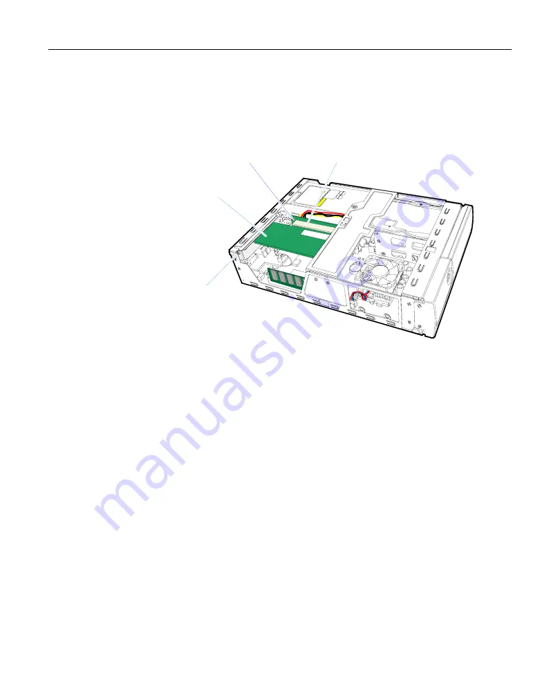
Install
the
PCI
Card
in
the
PCI
Riser
Card
slot.
Note:
You
may
have
to
temporarily
loosen
the
Riser
Card
Retaining
Screw
and
reposition
the
Riser
Card
slightly
in
order
to
install
the
PCI
Card.
21601
PCI Retaining Screw
Riser Card Retaining Screw
PCI Riser Card
PCI Card
3.
Secure
the
card
with
the
PCI
Retaining
Screw.
4.
Replace
the
screw
in
the
back
of
the
terminal.
5.
Replace
the
Top
Cover
cabinet.
Summary of Contents for RealPOS 30
Page 1: ...NCR RealPOS 30 7446 Release 2 1 User Guide 2 B005 0000 1551 Issue E ...
Page 90: ......
Page 98: ...3 8 Chapter 3 Setup ...
Page 148: ...A 10 Appendix A Cables ...


