background image

Model 6700 Family User’s Manual

15

9.

With a loopback connector in place, press
the 

TEST 

key to perform the I/O test…

PASS 

or 

FAIL 

is displayed briefly, then

I/O

.


This test is only valid on 9-pin or

15-pin models configured as “RS” units.

10. Press the 

ZERO 

key . . .

DIV-A


is displayed. This stands for the

high resolution DIVISION TEST W/AZT
enabled. See note at left.

11. Press the 

TEST 

key to perform this test…

The display shows the weight on the
scale at a resolution of 100,000 counts.

12. Press the 

TEST 

key to stop the test…

DIV-A

 is displayed.

13. Press the 

ZERO 

key…

DIV-N

 is displayed. This stands for the

high resolution DIVISION TEST w/o AZT
enabled.

14. Press the 

TEST 

key to perform this test…

The display shows the weight on the
scale at a resolution of 100,000 counts.

15. Press the 

TEST 

key to stop the test…

DIV-N


is displayed.

16. Press the 

ZERO 

key…

LN FR 

is displayed. This stands for line

frequency.

17. Press the 

TEST 

key...

The current line frequency (50 or 60) is
displayed.

DIAG will flash every
15 seconds during the
high resolution test as
a reminder that you
are doing a test and
not seeing normal
weight readings.

The remaining
selections are for
viewing current
settings only. You can
scroll through the
menu to verify the
settings, but to make
changes, you must
enter configuration or
calibration.

9-Pin RS-232 models:

On 15-Pin “RS” units,
jumper from Pin 1 to 2.

Summary of Contents for 6720

Page 1: ...User s Manual Model 6700 Family Model 6720 Model 6702 Model 6710 Point of Sale Interface Scales...

Page 2: ...ectrical shock Do not remove cover No user serviceable parts inside Refer servicing to qualified service personnel Weigh Tronix reserves the right to change specifications at any time CAUTION 03 12 02...

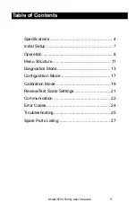
Page 3: ...ications 4 Initial Setup 7 Operation 8 Menu Structure 11 Diagnostics Mode 13 Configuration Mode 17 Calibration Mode 19 Review Test Scale Settings 21 Communication 22 Error Codes 24 Troubleshooting 25...

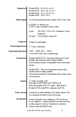
Page 4: ...ant Weights and Measures normally requires inspection of scale before scale is placed into operation Model Capacity lb Capacity kg 6702 7 15 x 005 7 x 002 6702 15 30 x 01 15 x 005 6710 7 15 x 005 7 x...

Page 5: ...load protection Adjustable center and side stops Model 6720 Die cast aluminum base with a stainless steel weigh platter Overload protection Adjustable center stop fixed corner stops high six digit LCD...

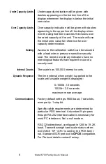
Page 6: ...a lead wire or pressure sensitive security seal The remote or primary indicators have no metrological features that require the use of a security seal The scale has 100 000 internal counts The time i...

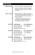
Page 7: ...use the dimensions on the following page to guide construction Scale Dimensions Min Cut Out Dimensions D 10 4 in 26 4 cm 11 1 in 28 2 cm W 6 4 in 16 3 cm 7 1 in 18 0 cm H 2 5 in 6 35 cm Adjustable to...

Page 8: ...cale can support more than one display however only one keypad is oper able Switch 3 selects internal or external display keypad operation Switch 3 Settings Closed internal display keys operational Op...

Page 9: ...The TEST key can be used to perform the initial power up test sequence recall diagnostic routines or to view the scale configu ration information This key also acts as YES or ACCEPT in the Menu mode T...

Page 10: ...the scale s function CAL Calibration Mode To calibrate the scale CONF Configuration Mode To configure the scale for your application The structure for these menus is shown in Figure 3 Specific informa...

Page 11: ...Model 6700 Family User s Manual 11 Figure 3 Menu Structure...

Page 12: ...acity Alternative Capacity Calibration Weights 9 995 lb 10 lb 15 x 005 lb 10 15 lb 7 x 002 kg 7 kg 9 995 kg 10 kg 30 x 01 lb 10 20 30 lb 15 x 005 kg 10 15 kg 60 x 02 lb 10 30 60 lb 30 x 01 kg 10 20 30...

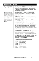
Page 13: ...back into the receive channel and verified against what was sent Requires a jumper short between transmit and receive data lines DIVISION TEST w AZT DIV A Weight data is normalized to 100 000 counts...

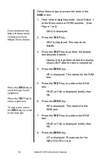
Page 14: ...1 or 2 DIAG is displayed 2 Press the TEST key DISP is displayed This stands for display 3 Press the TEST key to perform the display test described earlier Display test is performed and the display sho...

Page 15: ...his stands for the high resolution DIVISION TEST w o AZT enabled 14 Press the TEST key to perform this test The display shows the weight on the scale at a resolution of 100 000 counts 15 Press the TES...

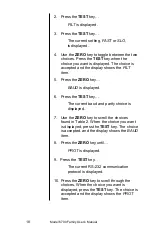
Page 16: ...col selection is displayed 20 Press the ZERO key BAUD is displayed This stands for baud rate 21 Press the TEST key The current baud rate and parity selec tion is displayed 22 Press the ZERO key CAP is...

Page 17: ...standard ECR Cash register compatible 8213 8213 compatible Sharp 2250 2250 compatible Swintec 34 F 34 MF compatible Sweda Mexico ATT AT T compatible o4000 Olympia Cash Register compatible Access the M...

Page 18: ...splayed 6 Press the TEST key The current baud and parity choice is displayed 7 Use the ZERO key to scroll the choices found in Table 2 When the choice you want is displayed press the TEST key The choi...

Page 19: ...e normal weighing mode move Switch 1 to the Menu mode or OPEN position Press the ZERO key until CAL is displayed 2 Press the TEST key 50 H or 60 H is displayed This is the AC line frequency 3 Press th...

Page 20: ...weights on the scale and press the TEST key After a brief wait DONE is displayed 8 Remove all calibration weights from scale 9 Press the TEST key DIAG is displayed or return Switch 1 to the closed po...

Page 21: ...iew the current system settings press and hold the TEST until the display shows dashes _ _ _ _ Release the TEST key and the display will prompt DISP and the scale is now in the Review Test Mode Press...

Page 22: ...RS 232 communication only Serial commands will be responded to only when the scale is in the normal operating mode and Switch 1 on the main board is in the CLOSED position Baud Rates 1200 2400 4800 96...

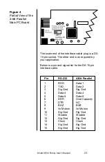
Page 23: ...al list for the DA 15 pin interface cable Pin RS 232 4 Bit Parallel 1 RXD Data 1 2 TXD Data 2 3 Sig Gnd Sig Gnd 4 Data 4 Data 4 5 Data 8 Data 8 6 DSR Over Capacity 7 DTR NC 8 BHZ BHZ 9 In Motion In Mo...

Page 24: ...4 JMP 1 4 DTR OUT 5 SG 5 GRD 6 JMP 1 6 DSR IN 7 JMP 2 7 RTS OUT 8 JMP 2 8 CTS IN 9 NC 9 RI IN Any system errors detected by the scale will be displayed as the letter E followed by a two digit error c...

Page 25: ...oard 4 Replace the main board Missing or extra segments on display 1 Replace the display board 2 Replace the main board Scale will not return to zero or incorrect weight is displayed 1 Press the ZERO...

Page 26: ...then power up the scale 4 Recalibrate the scale 5 Replace the load cell 6 Replace the main board Display shows center _ _ _ _ dashes Indicates that the scale is outside zero capacity of 2 1 Verify tha...

Page 27: ...PCB 4 Replace the display cable 5 Replace the main PCB DESCRIPTION PART NUMBER Keyboard Panel 1163 13205 Display PCB 7405 15465 RS 232 PCB 7405 14704 2 4 Bit Parallel PCB 7405 14653 2 40 Bit Serial P...

Page 28: ...Model 6700 Family User s Manual 28 Notes...

Page 29: ...Model 6700 Family User s Manual 29...

Page 30: ...Model 6700 Family User s Manual 30...

Page 31: ...Model 6700 Family User s Manual 31...

Page 32: ...1000 Armstrong Drive Fairmont MN 56031 Telephone 507 238 4461 Facsimile 507 238 4195 E Mail service wt nci com www wt nci com...

Reviews: