TRUE ROUND FIRE & FIRE/SMOKE DAMPER INSTALLATION,
OPERATION & MAINTENANCE INSTRUCTIONS
IOM - TRUE ROUND FIRE & FIRE/SMOKE DAMPERS - 1016
NCA MANUFACTURING INC. • 1985 CARROLL ST. • CLEARWATER, FL 33765 • 727.441.2651 • www.ncamfg.com
4
2 ANGLE METHOD INSTALLATION:
Guidelines:
The Two Angle Method (Figure 4) is approved for the
following:
A.
Masonry/concrete or stud/gypsum partitions
B.
1 ½ Hour rated True Round Fire or Fire/Smoke Dampers
C.
Vertical or horizontal orientation
D.
All UL approved sizes shown in Table 1 on page 2 of this
IOM
In this install method, the damper shall be installed in a stud/
gypsum or masonry fire partitition in the vertical or horizontal
position (blade shaft running horizontally within the parameters
of Detail A) with a retaining plate flush against both sides of the
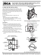
fire partition (see Figure 4).
Installation:
1.
With the factory installed retaining plate flush to the fire
partition, place another retaining plate (if manufactured
in the field - see Figure 5) on the opposite side of the damper
sleeve and slide it forward until it becomes flush with the
opposite side of the partition.
2.
Place the Splice Clip (see Figure 3 on page 3) over the cut
portion of the retaining plate and secure it with 4 - #10 sheet
metal screws or rivets as shown in Figure 4.
3.
Secure the clip angles (see Figure 3 on page 3) to the
retaining plate and damper sleeve as illustrated in Figure 4,
6 and 7.
D
B
2
Cut (Cover with
Splice Clip)
A
B
D
2
+ 1-1/2”
(38 mm)
All dimensions in inches
A and B = Damper Dia.
plus 3” (76 mm)
Blade
Shaft
Auxiliary
Operating
Jackshaft
1” Min. Typ.
(25.4 mm)
Clearance
Factory Supplied
Plate
Angle
Damper
Sleeve
Retaining
Plate
Fastener
Clip
Angle
UL Approved Wall
or Floor Design
Figure 4: Angles on 2 Sides
with Splice Clips
Typical masonry or metal stud opening. (Refer to the Framing
Requirements for Wood or Steel Stud Walls For Fire and Fire/
Smoke Dampers In Drywall Partitions).
Figure 5: Retaining Plate Detail
Figure 6:
Figure 7: Cross Section of
Damper in a Wall (Floor Similar)
Axle
30˚
+/- 30˚ Max. Off Horizontal
(in either direction)
Detail A
2 Angle
Installation Method
Splice Clip
(see Fig. 3)


