TRUE ROUND FIRE & FIRE/SMOKE DAMPER INSTALLATION,
OPERATION & MAINTENANCE INSTRUCTIONS
IOM - TRUE ROUND FIRE & FIRE/SMOKE DAMPERS - 1016
NCA MANUFACTURING INC. • 1985 CARROLL ST. • CLEARWATER, FL 33765 • 727.441.2651 • www.ncamfg.com
3
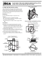
FIRE & FIRE/SMOKE DAMPER SLEEVES & MOUNTING CLIPS:
Damper Sleeves:
All true round fire and fire/smoke dampers must have an
integral sleeve (see Figure 1).
Guidelines:
1.
Sleeves must be of the SAME GAUGE or heavier than
the duct to which it is attached if one of the UL approved
breakaway connections is used (see seperate “UL App-
roved Breakaway Duct Connections” supplement).
2.
Gauges shall conform to SMACNA or ASHRAE duct
standards.
3.
Sleeves shall not extend beyond the fire barrier more
than 16” (406mm) on the operator side or 6” (152mm) on the
opposite side.
4.
The connecting duct shall terminate at the
integral sleeve and is connected by using either of the
following:
A.
Minimum of 3 - #10 sheet metal screws spaced equal
distance around the sleeve for 22” (559mm) and ~
smaller duct.
B.
Minimum of 5 - #10 sheet metal screws spaced equal
distance around the sleeve for greater than 22”
(559mm) duct.
C.
4” (101mm) drawband.
5.
Clearance between the damper sleeve and the round or
square wall opening shall be a minimum of 1/2” (13 mm)
and a maximum of 1” (25mm).
Note:
When installing the round damper into a square
opening, these clearances refer to the middle point of each
side of the square, not the corners.
6.
Damper will be factory supplied with one retaining plate
secured to the damper sleeve on the operator side of the
damper.
Mounting Clips:
A minimum of 4 equally spaced 20 gauge galvanized steel clip
angles (see Figure 3) shall be attached to both the integral
sleeve and the retaining plate (see Figures 1 and 2). The clip
angles shall be attached with 1/8” (3.2mm) rivets, #10 x
1/2” (12.7mm) steel metal screws, bolts or welds.
Note:
In metal stud/gypsum applications, the retaining plate
may be in front of or behind the gypsum, directly against the
metal studs.
1-1/2”
(38 mm)
Clip Angle Detail 20 Ga.
(1) Galv. Steel
1-1/2”
(38 mm)
1-1/2”
(38 mm)
Splice Clip Detail
1-1/2”
(38 mm)
Same length as
cut in damper/
retaining plates
Figure 1: Angles on 2 Sides
Figure 2: Angle on 1 Side
Figure 3: Mounting Clips
Typical stud or masonry opening. (Refer to the Framing Requirements for
Wood or Steel Stud Walls For Fire and Fire/Smoke
Dampers In Drywall Partitions)
Typical masonry or metal stud opening. (Refer to the Framing Requirements
for Wood or Steel Stud Walls For Fire and Fire/Smoke
Dampers In Drywall Partitions)
Splice Clip
(see Fig. 3)
Splice Clip
(see Fig. 3)


