BIM 1020/2005/03
3
www.nord.com
AXIAL RETENTION
Each drive shaft must be retained in place relative to the gear
reducer. Or each gear reducer must be retained in place relative
to the drive shaft. Either way NORD recommends the use of
shaft shoulders, locking collars or FIXING ELEMENTS to axially
retain the shaft or gear reducer in position.
SET SCREWS
If set screws are used for axial retention, they should be tightened
evenly. Flats may be filed on the driven shaft and a thread-
locking adhesive used for more position retention.
SNAP RING RETENTION
Placing external snap rings on drive shafts must be performed
with caution. The groove, which the snap ring fits into, may
weaken the drive shaft causing premature failure. NORD does
not recommend this type of shaft retention.
THRUST PLATE
In applications, which are subject to high vibratory loads, a thrust
plate will provide greater resistance to axial movement. Follow
the manufacturer’s recommendations for assembly.
SHRINK DISC
If a shrink disc is used to secure a reducer hollow shaft to the
driven shaft, follow this assembly procedure. Start with the shrink
disc mounted onto the extension of the hollow shaft disc locking
bolts loosened.
1.
Clean reducer bore and mating solid shaft to be free of any
lubricants or dirt.
2.
Slide reducer onto the solid shaft until it is about half way
through.
3.
Lubricate the remaining portion of the solid shaft with a #2
grease or similar lubricant. This part will be located under
the bronze bushing.
Do not install grease under the
shrink disc gripping area.
Finish installing the solid shaft
into the reducer hollow bore.
4.
Finger tighten all shrink disc bolts. Now, moving a circular
pattern, tighten each shrink disc locking bolt 1/4 to 1/2 turn.
Do not use criss cross pattern.
Continue tightening in the
same circular direction with 1/4 or 1/2 turn increments until
all bolts reach the specified bolt tightening torque. Bolt
tightening torque is shown on the shrink disc label for the
particular unit.
5.
Run unit for 24 hours, then retighten shrink disc locking bolts
to the proper bolt torque as indicated above.
TORQUE REACTION ARM
On the shaft mount ‘Clincher’, torque is reacted through the
integral torque tab, which is part of the casting. Commonly,
NORD’s optional RUBBER BUFFER bushings are installed on
each side of the integral torque tab to dampen torque shocks and
allow for mis-alignment received from the machinery during
operation.
Torque arm connection fabrications should always be mounted
perpendicular to a line through the output shaft center and the
point at attachment of the torque arm to the unit housing. In this
position the minimum load on the attachment structure arm will be
experienced. The attachment structure must be rigid and may not
deflect under any load. Doing so will place extra loads on the
output bearings of the reducer.
PRIME MOVER MOUNTING
AIign the prime mover to the reducer-input shaft using shims
under the feet. Make sure that the feet are supported. DoweI the
prime mover to its foundation.
SHAFT CONNECTIONS
When connecting shafts to either the input or output of the
reducer, consider the foIIowing instructions.
FITS
CIearance or interference fits for coupIing hubs shouId be in
accordance with ANSI/AGMA 9002-A86 or as follows.
Output and Input shaft Diameter toIerance
Metric
(mm)
d
18 = +0.012/+0.001
!
18
d
30 = +0.015/+0.002
!
30
d
50 = +0.018/+0.002
!
50
d
80 = +0.030/+0.011
!
80
d
120 = +0.035/+0.013
!
120
d
180 = +0.040/+0.015
Inch
d
1.750 = +0.0000/-0.0005
!
1.750 = +0.0000/-0.0010
Output and Input shaft DriII and tap shaft end
Metric (mm)
d
16 = M5
!
16
d
21 = M6
!
21
d
24 = M8
!
24
d
30 = M10
!
30
d
38 = M12
!
38
d
50 = M16
!
50
d
85 = M20
!
85
d
130 = M24
Inch
d
0.438 = #10-24 x 0.4 deep
!
0.438
d
0.813 = 1/4-20 x 0.6 deep
!
0.813
d
0.938 = 5/16-18 x 0.7 deep
!
0.938
d
1.125 = 3/8-16 x 0.9 deep
!
1.125
d
1.375 = 1/2-13 x 1.1 deep
!
1.375
d
1.875 = 5/8-11 x 1.4 deep
!
1.875
d
3.250 = 3/4-10 x 1.7 deep
!
3.250 = 1-8 x 2.2 deep
Outboard pinion and sprocket fits shouId be as recommended by
the pin sprockets with interference fits shouId be heated
according to the manufacturer’s recommendations, generaIIy
250
q
F to 300
q
F, (120
q
C to 150
q
C) before assembIing to the shaft.
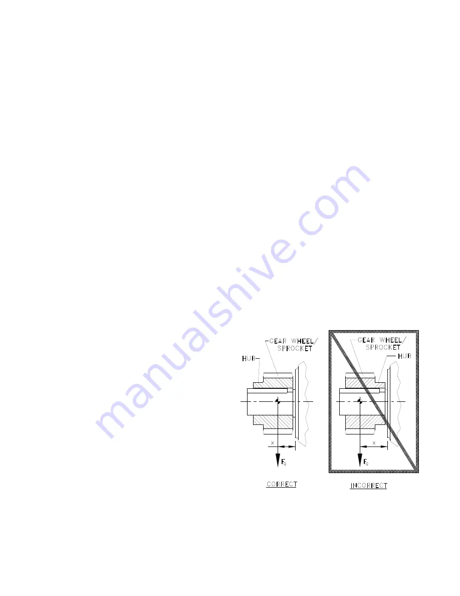
LOCATION
CoupIing hubs shouId be mounted fIush with the shaft ends,
unIess specificaIIy ordered for overhung mounting. Pinions,
sprockets and sheaves shouId be mounted as cIose as possibIe
to the unit housing to minimize bearing Ioads and shaft
defIections.
Summary of Contents for Brawn mixer BTO Series
Page 2: ...THIS PAGE IS INTENTIONALLY LEFT BLANK...
Page 4: ......
Page 6: ......
Page 36: ...THIS PAGE IS INTENTIONALLY LEFT BLANK...
Page 37: ...THIS PAGE IS INTENTIONALLY LEFT BLANK...
Page 38: ...THIS PAGE IS INTENTIONALLY LEFT BLANK...
Page 39: ...THIS PAGE IS INTENTIONALLY LEFT BLANK...
Page 40: ......


