Navkom Bioreader Instruction Manual Download Page 4

48

EN

EXTERNAL UNIT - FINGERPRINT READER

COMPONENTS AND THEIR FUNCTIONS

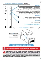
Our fingerprint readers can be installed in different configurations with different control units:

OPTION 1: Fingerprint door leaf control unit

OPTION 2:  Fingerprint DIN rail control unit

OPTION 3:  Fingerprint mini control unit BBX (site 65)

CONTROL UNITS AND WAYS TO OPERATE A FINGERPRINT READER

1

MULTICOLOR LED

2

FINGERPRINT SENSOR

It provides different signals about 

the status of the device and operations.

Always in standby mode. When a suitable fingerprint is

placed on it, the door will open immediately.

3

BEEPER

It provides sound signals to complement 

the LEDs during operations.

1

2

3

TEHCHNICAL DATA

• 

Fingerprint capacity: 500

• 

Power supply voltage: 12/24 V, AC

• 

2 relay outputs, Mini control unit BBX 1 relay output 40V/1A

• 

Maximum current/voltage on the relay:  40V/3A

• 

Relay triggering time: 1 - 10 s

• 

Maximal power: 3,6 W

• 

Fast fingerprint recognition: <1,2 s

• 

Operating temperature range: -30 ºC do +80 ºC

• 

Maximum environmental humidity: 100 % IP65

• 

Fingerprints will remain in the memory in the case of power failure.

• 

Area capacitive sensor FPC1011F3

• 

User interface: 5-colour LED, beeper, buttons on the control and a smartphone app

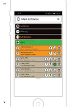
Summary of Contents for Bioreader

Page 1: ...EN INSTRUCTION MANUAL...

Page 2: ...8 CONTROL UNITS ANDWAYSTO OPERATE A FINGERPRINT READER 48 COMPONENTS ANDTHEIR FUNCTIONS 48 FIRST CONNECTIONTOTHE READER 49 THE RELAY 2 50 FINGERPRINT READER SECURITY LOCKDOWN 50 THE READER ANDTHE CONT...

Page 3: ...to be pressed on the sensor more firmly than usual in order to recognize it the most common cause is dry skin This can happen more often in winter months We can moisten our fingerprints with a help o...

Page 4: ...ys in standby mode When a suitable fingerprint is placed on it the door will open immediately 3 BEEPER It provides sound signals to complement the LEDs during operations 1 2 3 TEHCHNICAL DATA Fingerpr...

Page 5: ...access the button unscrew the bolt first CONTROL UNIT INSTALLED IN A DOOR LEAF OPTION 1 BUTTON 1 BUTTON 2 BUTTON R 1 2 3 DIN RAIL CONTROL UNIT OPTION 2 FIRST CONNECTIONTOTHE READER WHEN X MANAGER APP...

Page 6: ...LY YOU ARE NOT ABLETO USEYOUR DEVICE DURINGTHIS PERIOD 1 Press the R button on the DIN control unit and hold it for 10 seconds 2 Toaccessthebuttononthedoorleafcontrolunit unscrewtheboltfirst Pressthe...

Page 7: ...Enter the name of the device and press ADD 2 A SINGLE READER CAN BE CONNECTEDTO MORETHAN ONE DEVICE X MANAGER APP Press the i icon next to the name of the reader on the device which has already estab...

Page 8: ...ION BEFORE IT CAN BE USED IF MORETHAN ONE READER IS CONNECTEDTO A SINGLE X MANAGER APPLICATION IT IS IMPORTANTTHATTHE FIRST CONNECTION IS ESTABLISHEDWITH ONE READER AT ATIME THE REST OFTHE READERS SHO...

Page 9: ...ion to the reader After prompted press Show password The password will appear on the lower portion of the screen Write it down 1 On the new device press and in the next step chose the option Manual Se...

Page 10: ...54 EN 1 2 3 4...

Page 11: ...open the door Choose the relay that the person will trigger relay 1 relay 2 or relays 1 and 2 together Not valid for mini control unit BBX 1 or 3 fingerprints for the person are enrolled Fingerprints...

Page 12: ...56 EN...

Page 13: ...ger You can enroll additional fingerprints of any person at any time By pressing 1 icon one fingerprint will be enrolled By pressing 3 icon three fingerprints will be enrolled Users can have schedules...

Page 14: ...58 EN 1 2 3 4 5 6 7...

Page 15: ...Fingerprint database can be transferred from one reader to another 1 Press the Export button on the source reader This is confirmed by an administrator 2 Make the connection to the new reader and pres...

Page 16: ...60 EN...

Page 17: ...l entries users and administrators 0 all attempts of entry outside the scheduled time the schedule must be turned on and assigned to a user 0 temporary lock downs The history cannot be deleted The new...

Page 18: ...62 EN 1 2 3 4 5 6...

Page 19: ...e desired settings press the SAVE button 4 When the schedule is saved it automatically becomes active This is indicated by the green Power icon Each schedule can be deactivated by pressing the Power i...

Page 20: ...1 2 64 EN...

Page 21: ...PHONE IS CONNECTEDTO ONTHE POWER SUPPLY FOR 6O SEC all fingerprints stored in the memory including administrator fingers will be erased and the device will be reset to factory settings Connection with...

Page 22: ...xtended for the time the product was at service If the respective product has undergone a major service interven tion or if the product was replaced a new warranty is issued to the customer for a 36 m...

Reviews: