background image

Navini Networks, Inc.  


     Ripwave Wireless Broadband Access Card User’s Guide 

Navini Networks, Inc.  


     Ripwave Wireless Broadband Access Card User’s Guide 

Page 21 

060210_pv1.7_Ripwave Wireless Broadband Access Card User’s Guide_40-00292-00d(4.4.2)


The Signal Strength and 
Signal Quality Bars, 
continued 
 

How to Increase 
the Strength and 
Quality of the 
Signal 


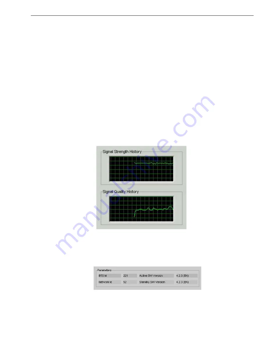
The History Graphs 


The Parameters 


to 13 but less than or equal to 21. Red lines indicate a weak signal 
or an SNR less than 13. 
 
 
To increase the strength and quality of the signal, change the 
location of the PC in which the Card is inserted. Try moving it 
closer to a window, to a higher location, away from other wireless 
devices (microwave ovens, cordless phones), and away from metal 
objects (shelves, file cabinets). As you reposition your PC, watch 
the Signal Strength and Quality bars on the NavDiag screen. Place 
your PC in the location where you receive the most green signal 
strength and quality bars. 
 
 
The History graphs plot the change in signal strength and signal 
quality over time. The graphs cover the last minute and are updated 
every second. Read the graphs from right to left. The right side of 
the graph represents the most recent status of your Card. 


At the bottom of the Connection Status screen are four parameters. 
These parameters are BTS ID, Network ID, Active SW Version, 
and Standby SW Version.  

 
The BTS ID indicates the BTS to which the Card is currently 
synchronized. The Network ID indicates the network in which  
the Card is operating. Active SW Version and Standby SW Version 


Page 21 

060210_pv1.7_Ripwave Wireless Broadband Access Card User’s Guide_40-00292-00d(4.4.2)


Summary of Contents for 40-00292-00

Page 1: ...se er r s s G Gu ui id de e Part Number 40 00292 00 Revision D Version 1 0 PV1 7 February 10 2006 Proprietary All information disclosed by this document is the proprietary property of Navini Networks...

Page 2: ...SIGNAL STRENGTH AND SIGNAL QUALITY BARS 20 HOW TO INCREASE THE STRENGTH AND QUALITY OF THE SIGNAL 21 THE HISTORY GRAPHS 21 THE PARAMETERS 21 THE SCREEN OPTION BUTTONS 22 THE CONFIGURATION SCREEN 22 TH...

Page 3: ...i Networks Inc Navini Networks is a registered trademark The Navini Networks logo Zero Install Ripwave and Unwired by Navini are trademarks of Navini Networks Inc Other product and company names menti...

Page 4: ...ith the equipment 2 Do not use the equipment while you are in a bathtub shower pool or spa Exposure of the equipment to water could cause severe electrical shock or serious damage to the equipment 3 D...

Page 5: ...nder the following conditions When the equipment has been exposed to water or moisture When the equipment has been damaged When the equipment does not operate properly or shows a distinct change in pe...

Page 6: ...correct the interference by one or more of the following measures 1 Reorient or relocate the receiving antenna 2 Increase the separation between the equipment and the receiver 3 Consult the dealer or...

Page 7: ...ither 2 5 2 6 GHz 3 4 GHz or 3 5 GHz The frequency number appears on the Card s label The various models are detailed in the table below Model Frequency Range Operating Band 2 5 2 6 GHz 2 500 GHz 2 68...

Page 8: ...8 pin connector Depending on which model you have one or two internal inverted F antennas reside inside the card The 2 5 2 6 GHz model has one internal inverted F antenna while the 3 4 and 3 5 GHz mod...

Page 9: ...ere taken from a laptop operating with Windows 2000 If you have a Windows 98 XP or ME operating system the screens you see may vary from the screens shown in the instructions Step Action Illustration...

Page 10: ...for my device recommended Click Next to continue Windows 2000 Screen 6 The Locate Driver Files box appears Select CD ROM Insert the Installation CD into the computer s CD ROM drive Click Next to conti...

Page 11: ...eard Note Windows 98 XP or ME systems may show a screen stating the PCMCIA Adapter has not passed Windows Logo testing and asking if you want to continue installation Select the option that continues...

Page 12: ...d from the PC Also turn the antenna to its original down position Leaving the Card in the PC or the antenna in the upright position while storing the PC in a computer case may damage the card or the a...

Page 13: ...on the devices currently installed on your PC For example Select Stop Navini Networks PCMCIA Adapter Next the Stop a Hardware Device dialog box appears Click OK You can now pull the Card out of your c...

Page 14: ...avDiag monitoring software or contact your Service Provider The NavDiag software assists you in solving connection problems and provides other valuable information This software is provided on the Ins...

Page 15: ...OM drive 3 Open the CD by clicking on the My Computer icon Double click on the folder named Navini_Diagnostics 4 Double click on the icon for the file navdiag_windows exe This will automatically start...

Page 16: ...e set on your PC under Regional Options The language selection affects how NavDiag displays its screens If you receive an error message concerning the language click OK and NavDiag will default to Eng...

Page 17: ...ept option and click Nex continue If Agreement is n accepted you cann install the software 10 rs to e he default installation The Choose Install Folder screen appea Enter the name of the folder where...

Page 18: ...Installation Summary screen appears Review the contents for accuracy Click Install to continue For your installation and computer this screen may have different information than what is shown in the i...

Page 19: ...ear on the top right side of the screen represent the PC the connection between the PC and the Modem the Modem the connection between the Modem and the Base Station and the Base Station to which the M...

Page 20: ...to Noise Ratio SNR received by your Modem Again the quality of the signal is represented by a group of colored bars The higher the pile of bars goes the better the SNR of the signal The color of the...

Page 21: ...ay from metal objects shelves file cabinets As you reposition your PC watch the Signal Strength and Quality bars on the NavDiag screen Place your PC in the location where you receive the most green si...

Page 22: ...rently loaded in t active side and standby side of the Card s flash memory The two letters in parenthesis following t On the left hand side of the screen there are five screen option b Statistics and...

Page 23: ...value of the selected parameters over the last five minutes updated once every second The graphic scrolls from right to left The Statistics screen lets you view the current value of selected paramete...

Page 24: ...me reason you need to uninstall the NavDiag software g to upgrade your Operating System software follow the rocedure below Note If you are going to upgrade your PC Operating System fter loading the Na...

Page 25: ...ft corner click on Start Programs NavDiag Uninstall 2 The Install Anywhere Unins Windows 2000 S taller screen appears Click creen Uninstall 3 The screen indicates the application files are uninstalled...

Page 26: ...hrough the Card antenna Following is a picture of the optional desktop antenna To connect the desktop antenna to the Card you must first remove the antenna attached to the Card To remove the antenna t...

Page 27: ...the Card hold the connector at its connection point and gently pull the connector o of the Card Note If a desktop antenna is required for optimal reception avoid frequently connecting and disconnecti...

Page 28: ...This may cause the card to become jammed inside the card slot The PC Card should fit easily into the PC slot Do not force the card into the PC slot Forcing the card into the slot may cause damage to...

Page 29: ...uring the OTA upgrade process If you must upgrade your software using this method your Service Provider will give you instructions on what to do This method takes a minimal amount of time to complete...

Page 30: ...orted 1 3 Win XP Supported 2 3 Note 1 Internet Explorer 3 0 or higher is required ote 2 Requires Service Pack 1 ote 3 To load the NavDiag software the user MUST have Administrative privileges esults o...

Page 31: ...us SUCCESSF stall File C Program Files Na Status SUCCESSFUL stall File C Program Files Na Status SUCCESSF L ake Registry Entry Key KEY_LOCAL_MACHINE SOFT ARE Microsoft Windows CurrentVersion Uninstall...

Page 32: ...File C Program Files NavDiag data images splash gif Status SUCCESSFUL Install File C Program Files NavDiag data images buttonbar gif Status SUCCESSFUL Install File C Program Files NavDiag data images...

Page 33: ...Files NavDiag data lib navDiag jar Status SUCCESSFUL Install File C Program Install File C Program Files NavDiag data lib jcommon 0 8 8 jar Status SUCCESSFUL Install File C Program Files NavDiag data...

Page 34: ...ns of this nce for the benefit of Navini to destroy or return the Software and all copies at such time as Buyer chooses to cease using the Software or upon termination or cancellation of this ownershi...

Page 35: ...r in FAR 48 CFR 52 227 14 June 1987 or DFAR 48 CF ARTICLE 3 1 Trade Secret Navini Networks Inc considers the licensed Software covered by this License Agreement to be a trade secret Navini Networks In...

Page 36: ...IMITATION OF LIABILITY L 5 1 Consequential Damages TO THE MAXIMUM EXTENT PERMITTED BY THE O EVENT SHALL NAVINI NETWORKS INC OR ANY ION PRODUCTION DELIVERY OR IRECT INCIDENTAL CONSEQUENTIAL OR PUNITIVE...

Page 37: ...responsible 6 3 for any damages indirect or direct and costs that Navini Networks Inc may incur if Buyer appoints a subcontractor who accesses the Software without Navini s prior written consent Buye...

Reviews: