9
INTERFACING GATEWAY TO DEVICES
4.2.1 Biasing the RS-485 Device Network
●
An RS-485 network with more than one device needs to have
biasing to ensure proper communication. The biasing only
needs to be done on one device.
●
The gateway has 510 ohm resistors that can be used to set the
biasing. The gateway’s default positions from the factory for the
biasing jumpers are OFF.
●
The OFF position is when the 2 red biasing jumpers straddle the
4 pins closest to the outside of the board of the gateway. (Figure
●
Only turn biasing ON:
-
IF the BMS cannot see more than one device connected to
the gateway.
-
AND all the settings (COM settings, wiring, and DIP
switches) have been checked.
●
To turn biasing ON, move the 2 red biasing jumpers to straddle
the 4 pins closest to the inside of the board of the gateway.
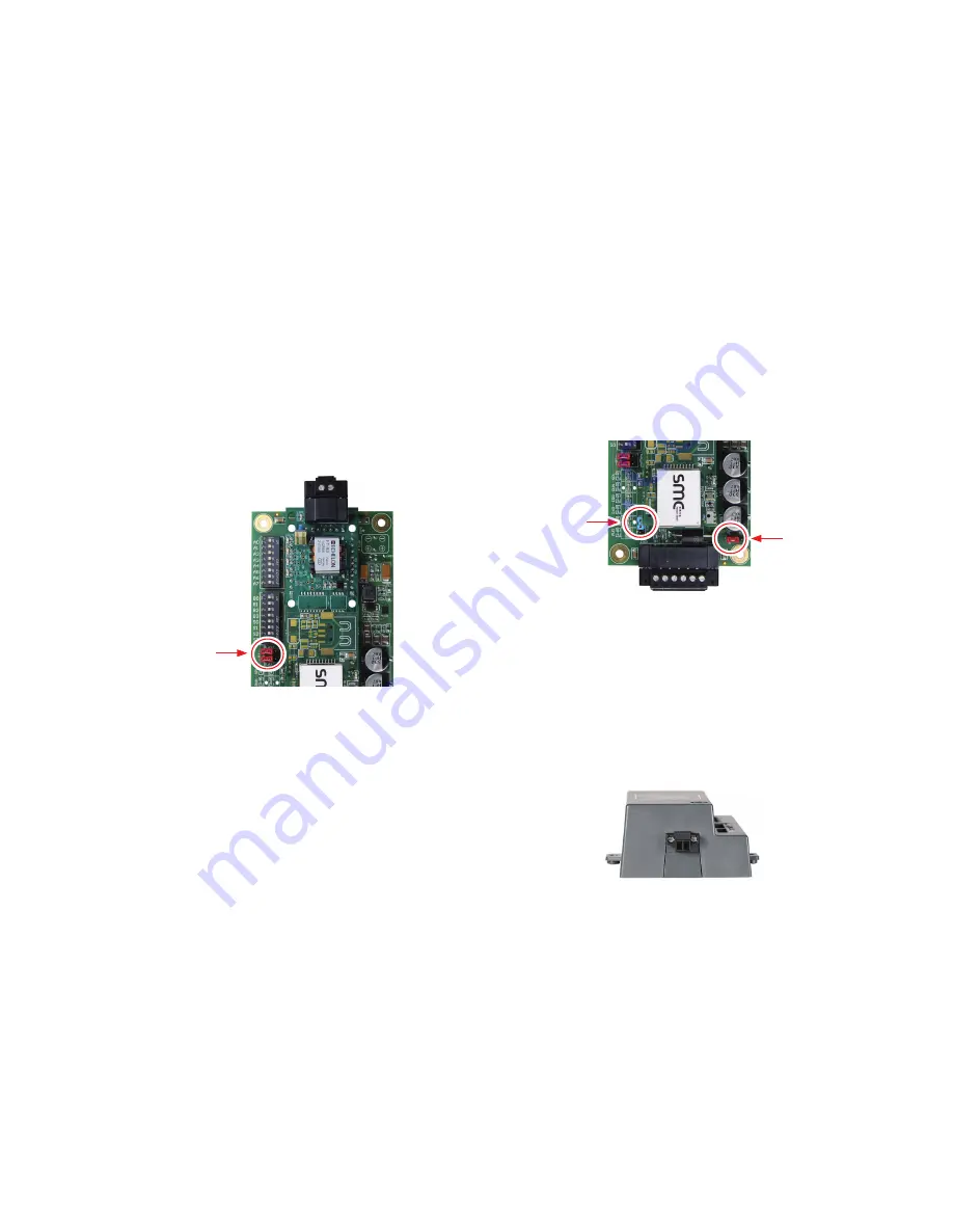
RS-485 Bias
Switch
(off)
Figure 8: RS-485 Biasing Switch on the Gateway
4.2.2 End of Line Termination Switch for the RS-485
Device Network
●
On long RS-485 cabling runs, the RS-485 trunk must be properly
terminated at each end.
●
The gateway has an end of line (EOL) blue jumper. The default
setting for this blue EOL switch is OFF with the jumper
straddling the pins closest to the inside of the board of the
gateway.
-
On short cabling runs the EOL switch does not to need to be
turned ON.
●
If the gateway is placed at one of the ends of the trunk, set
the blue EOL jumper to the ON position straddling the pins
closest to the outside of the board of the gateway.
●
Always leave the single red jumper in the A position (default
factory setting).
RS-485 EOL
Switch
(off)
Leave in
Position A
Figure 9: RS-485 End-Of-Line Termination Switch on the Gateway
4.3 Wiring LonWorks Devices to the
LonWorks Terminal
●
Wire the LonWorks device network to the LonWorks Gateway
Terminal.
-
Use approved cable per the FT-10 installation guidelines.
●
LonWorks has no polarity.
Figure 10: LonWorks Terminal


