8 |
P a g e
Agreement
:
End user agrees to use this product in compliance with all State and Federal laws. NAV-TV Corp. would not be held liable for misuse of its product.
If you do not agree, please discontinue use immediately and return product to place of purchase. This product is intended for off-road use and passenger
entertainment only.
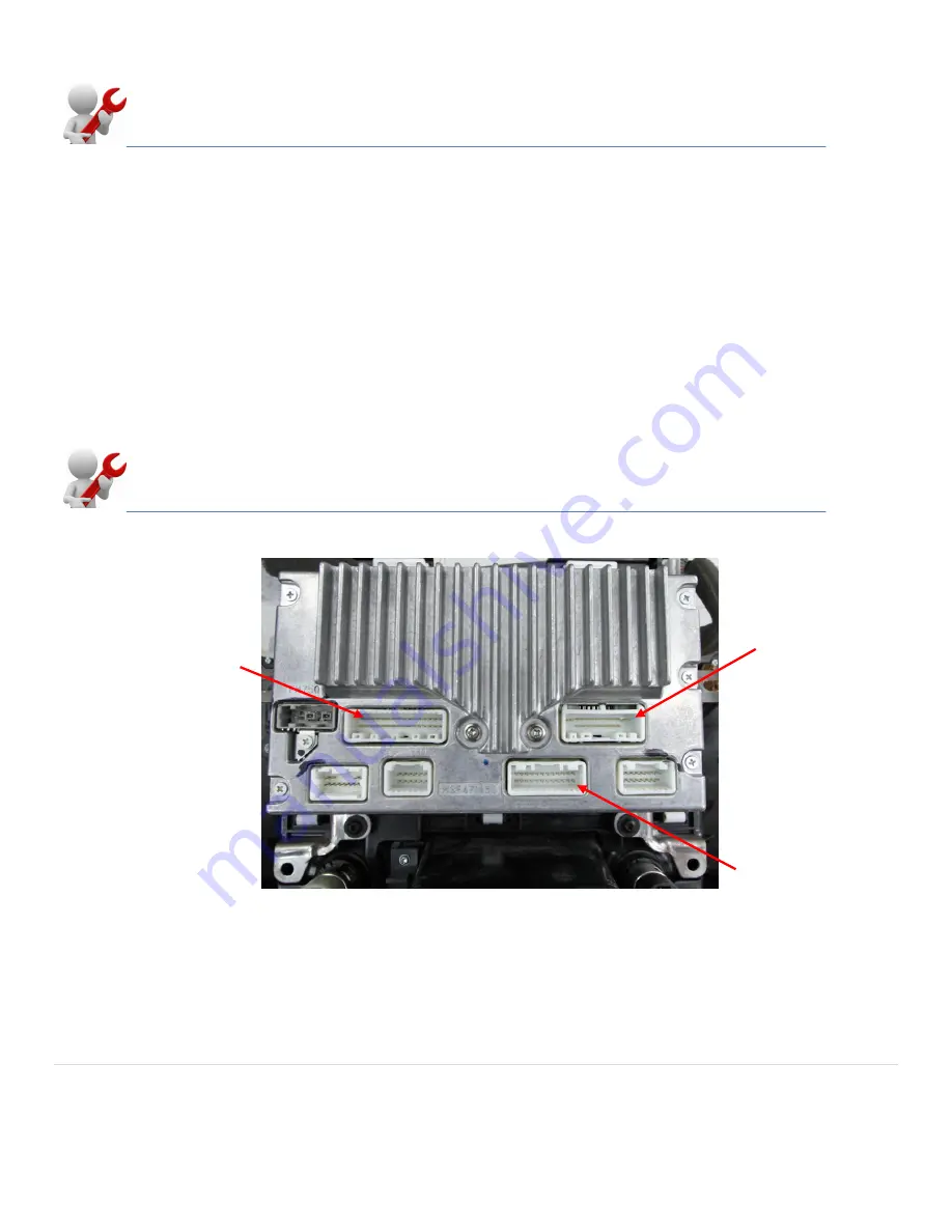
Location of the
factory reverse
signal (12 volt +
while in reverse)
Top row third pin in
from the top right
corner
Screen Replacement FX.
1.
Follow the directions on the previous page under "Screen Replacement All Vehicles Except FX" to remove the
factory monitor from the mounting bracket.
2.
The original monitor in the FX has an oversized monitor housing. In order to replace the original monitor with the
new touch screen monitor you must use the included (FX Kit only) trim, shims and longer replacement screws to
center the new monitor in the mounting brackets.
3.
Reinstall the new monitor and mounting bracket back into the vehicle and place the included (FX Kit only) trim
fascia around the new monitor. Note: The fascia is a pressure fit and does not require adhesive to stay in place.
Plug-and-play installation is performed at the radio for ALL VEHICLES.
At this stage the monitor should be reinstalled in the vehicle with the factory connector plugged into the monitor. If you
have failed to follow these instructions and ANY aftermarket harness is plugged in at the screen, disconnect it and
insert the factory plug. In vehicles where the screen mounts behind the fascia, like the Armada, the screen can be
reattached with the factory screws and mounted permanently. In vehicles like the G37 where the radio top mounts are
in the same location as the monitor bottom screws, reattach the top mechanical hinge mount but leave the bottom
retaining screws out until the installation is completed and only reattach during final reassembly.
BACK OF ALL RADIOS
20 Pin Power
Connector
24 Pin Video
Connector


