background image

12

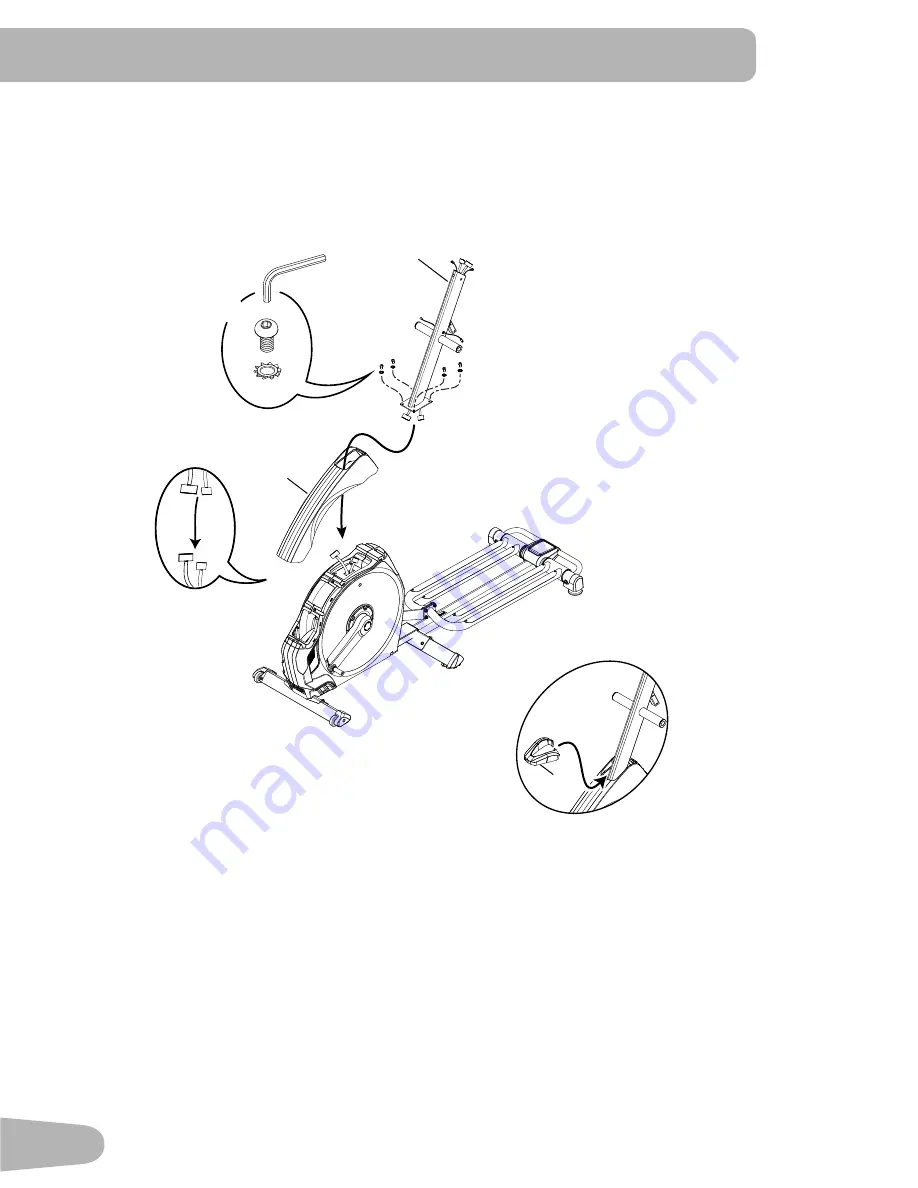
3. Connect the Cables and Attach the Console Mast to Frame Assembly

 NOTICE:

   Put the Console Mast through the opening in the Upper Shroud. Before you connect the cables, remove 

the wire tie that holds the Frame cables in place on the mount plate. Do not crimp cables. Fully tighten 

the hardware.

1

20

B

D

6mm

X4

21

Summary of Contents for E628

Page 1: ...ASSEMBLY MANUAL OWNER S MANUAL E628 ...

Page 2: ...nformation Serial Number __________________________ Date of Purchase ____________________ To register your product warranty contact your local distributor If you have questions or problems with your product please contact your local Nautilus distributor To find your local distributor go to www nautilusinternational com Nautilus Inc www nautilusinternational com Nautilus Inc 18225 NE Riverside Park...

Page 3: ...exposure to bystanders Some components of the machine can be heavy or awkward Use a second person when doing the assembly steps involving these parts Do not do steps that involve heavy lifting or awkward movements on your own Set up this machine on a solid level horizontal surface Do not try to change the design or functionality of this machine This could compromise the safety of this machine and ...

Page 4: ...o not put fingers or other objects into moving parts of the exercise equipment Set up and operate this machine on a solid level horizontal surface Make the Foot Pedals stable before you step on them Use caution when you step on and off the machine Disconnect all power before servicing this machine Do not operate this machine outdoors or in moist or wet locations Keep at least 0 6 m 24 on each side...

Page 5: ...5 SAFETY WARNING LABELS AND SERIAL NUMBER Serial Number 21 78mm 54 8mm Product Specification ...

Page 6: ...at the machine is correctly earthed Do not change the plug on the machine if it does not fit the outlet have a correct outlet installed by a licensed electrician If you connect the machine to an outlet with RCBO Residual Current circuit Breaker with Overload protection machine operation can cause the circuit to trip A Surge Protector Device is recommended to protect the machine If a Surge Protecto...

Page 7: ...mended wrenches turn the bolts and nuts to the right clockwise to tighten and the left counterclockwise to loosen unless instructed otherwise When attaching 2 pieces lightly lift and look through the bolt holes to help insert the bolt through the holes The assembly can require 2 people Maximum User Weight 158 8 kg 350 lbs Total Surface Area footprint of equipment 12 707 cm2 Maximum Pedal Height wi...

Page 8: ...d Right 19 1 Upper Right Handlebar Arm 6 1 Water Bottle Holder 20 1 Upper Shroud 7 1 Water Bottle Holder Shroud Left 21 1 Shroud Cap 8 1 Upper Left Handlebar Arm 22 1 Right Leg 9 2 Handlebar Shroud Outer 23 1 Right Pedal 10 2 Handlebar Shroud Inner 24 1 MP3 Cord 11 1 Rail Assembly 25 1 Power Cord 12 1 Arm Pivot Rod 26 1 Heart Rate HR Chest Strap 13 1 Left Leg 27 1 Silicone Lubricant Bottle not sho...

Page 9: ...hillips Head Self tap Screw M4 2x16 D 4 Button Head Hex Screw M8x16 J 4 Phillips Head Screw M5x12 E 2 Hex Head Screw M8x20 F 6 Wave Washer Note Select pieces of Hardware have been provided as spares on the Hardware Card Be aware that there may be remain ing Hardware after the proper assembly of your machine HARDWARE TOOLS Tools Included 6 mm A B C D E F G H I J 2 13 mm 15 mm 19 mm ...

Page 10: ...10 ASSEMBLY 1 Attach Front Stabilizer to Frame Note Hardware is pre installed and not on the Hardware Card 6mm X4 17 16 ...

Page 11: ... Note Hardware is pre installed and not on the Hardware Card Separate the Rail mount plates 11a and lift to align the holes and install the hardware The plastic scratch guard strips on the Rails help to protect the finish during assembly 11 11a ...

Page 12: ... Frame Assembly NOTICE Put the Console Mast through the opening in the Upper Shroud Before you connect the cables remove the wire tie that holds the Frame cables in place on the mount plate Do not crimp cables Fully tighten the hardware 1 20 B D 6mm X4 21 ...

Page 13: ...13 4 Attach Legs to Frame Assembly F X2 22 13 A C G X2 6mm ...

Page 14: ...TICE Route the cable 1a from the left side of the Mast to the rear of the crossbar and through the opening 7a in the Water Bottle Holder Shroud Do not crimp cables Repeat on the right side Install hardware and Water Bottle Holder Push down until it snaps in place I X5 6 ...

Page 15: ...15 6 Install Arm Pivot Rod and Lower Handlebar Arms to Frame Assembly Note Be sure to put Wave Washers F on Arm Pivot Rod before attaching the Lower Handlebar Arms 14 F X2 C G E X2 13 mm 12 18 ...

Page 16: ... Leg and Lower Handlebar Arm NOTICE Attach the Pedal to the Leg first Make sure the Pivot Sleeve H engages the Handlebar knuckle cover Repeat step on opposite side with the Right Pedal Item 23 23 15 H C H G A 6mm 15 A C G F 6mm ...

Page 17: ...ach the Upper Handlebar Arms to Frame Assembly NOTICE Hardware is pre installed and not on the Hardware Card Do not crimp the cables Make sure the Upper Handlebar Arms are secure before you exercise X8 19 8 6mm ...

Page 18: ...tic Handlebar and Attach Static Handlebar to the Console NOTICE Carefully place the Console face down on a padded surface Route the Console Cables through the Static Handlebar Attach the Static Handlebar to the Console using the screws that were removed in Step 9 Connect the Heart Rate Cable 4a from the Static Handlebar to the Console Heart Rate Cable Do not crimp the cables 3 2 X4 3 4 4a 2 X4 4a ...

Page 19: ... Mast NOTICE Hardware is pre installed and not on the Hardware Card Align the clips on the cable connectors and make sure the connectors lock Do not crimp cables Push the extra wire down into the Console Mast to allow pivot clearance 12 Attach the Console Junction Cover 2 6mm X3 ...

Page 20: ...ar Shrouds NOTICE Connect the cables Route the wire through the 3 guides inside the rear Handlebar Shroud and fit the connectors inside the cavity as shown Do not crimp cables Make sure the inner edge of the Handlebar Shroud is seated in the Water Bottle Holder Shroud 1a 9 10 1a 2X 1a 2X ...

Page 21: ...21 14 Attach Front Handlebar Shrouds and Install Screws NOTICE Do not crimp cables J 2X J 2X ...

Page 22: ... the plastic scratch guard strips from Rails Apply silicone lubricant to a cloth and wipe the Rails to eliminate roller noise Silicone lubricant is not intended for human consumption Keep out of reach of children Store in a safe place Be sure to record the serial number in the field provided at the front of this manual Do not use until the machine has been fully assembled and inspected for correct...

Page 23: ...re all physically fit and able to move the machine safely 1 Remove the power cord 2 Use the Transport Handle to carefully lift the machine onto the transport rollers 3 Push the machine into position 4 Carefully lower the machine into position NOTICE Be careful when you move the elliptical Abrupt motions can affect the computer operation BEFORE YOU START ...

Page 24: ...of the Rail Assembly for approximately 20 seconds 3 Step off the machine 4 Loosen the locking nuts and adjust the levelers until they all contact the floor Do not adjust the levelers to such a height that they detach or unscrew from the machine Injury to you or damage to the machine can occur 5 Adjust until the machine is level Tighten the locking nuts Make sure the machine is level and stable bef...

Page 25: ...tooth Connectivity not shown J Leveler X Heart Rate HR Chest Strap K Incline Arm Y MP3 Cord L Stabilizer Z Power Cord M Transport Roller AA Silicone Lubricant Bottle not shown N Power Connector Power Switch A B C D E F G H I J K L M N O P Q R S T U V A Y Z X WARNING Use the values calculated or measured by the machine s computer for reference purposes only The heart rate displayed is an approximat...

Page 26: ...angle of the Rail Assembly QUICK START button Begins a Quick Start workout USER button Selects a User profile PROGRAMS button Selects a category and workout program PAUSE END button Pauses an active workout ends a paused workout or goes back to the previous screen GOAL TRACK button Displays the Workout Totals and Achievements for the selected User Profile Increase button Increases a value age time...

Page 27: ...ity Display shows the level of work at that moment based on the current resistance level Heart Rate Zone Display The Heart Rate Zone shows which zone the current heart rate value falls into for the current User These Heart Rate Zones can be used as a workout guide for a certain target zone anaerobic aerobic or fat burn Consult a physician before you start an exercise program Stop exercising if you...

Page 28: ...istance display shows the distance count miles or km in the workout Note To change the measurement units to English Imperial or metric refer to the Console Setup Mode section in this manual Level The LEVEL display shows the current resistance level in the workout RPM The RPM display field shows the pedal revolutions per minute RPM Heart Rate Pulse The Heart Rate display shows the beats per minute ...

Page 29: ...mitter chest strap lets you monitor your heart rate at any time during your workout Consult a physician before you start an exercise program Stop exercising if you feel pain or tightness in your chest become short of breath or feel faint Contact your doctor before you use the machine again The heart rate displayed is an approximation and should be used for reference only The heart rate transmitter...

Page 30: ...ands must make contact with the sensors for the Console to detect a pulse After the Console detects four stable pulse signals your initial pulse rate will be shown Once the Console has your initial heart rate do not move or shift your hands for 10 to 15 seconds The Console will now validate the heart rate Many factors influence the ability of the sensors to detect your heart rate signal Movement o...

Page 31: ...minute Age 25 29 0 50 100 150 200 250 30 34 35 39 40 44 45 49 50 54 55 59 60 64 65 69 70 196 191 186 181 176 171 166 161 156 151 146 167 162 158 154 150 145 141 137 133 128 126 Maximum Heart Rate Target Heart Rate Zone keep within this range for optimum fat burning 118 115 112 109 106 103 100 97 94 91 88 Remote Resistance and Incline Controls The remote resistance and incline controls are located ...

Page 32: ... is recommended to adjust both Pedals to the same setting To adjust the Pedal 1 Tilt the back of the Pedal up 2 Lift the adjustment lever out of the notch for the current setting and move it to the desired setting Be sure the lever is engaged in the notch at the new setting Mounting and Dismounting the Machine Care should be used when mounting or dismounting the machine Be aware that the Pedals an...

Page 33: ...ase Decrease buttons to adjust between MILES Imperial English or KM metric 6 Push OK to set The Console goes back to the Power Up Idle Mode screen Note To adjust these selections consult the Console Set Up Mode section Quick Start Manual Program The Quick Start Manual program lets you start a workout without entering any information During a Manual Workout each column represents a 2 minute time pe...

Page 34: ...e Note The User name will be blank if this is the first edit The name of a User Profile is limited to 10 characters The currently active segment will flash Use the Increase Decrease buttons to move through the alphabet and blank space found between A and Z To set each segment use the Left or Right buttons to shift between segments Push the OK button to accept the displayed User name 5 To edit the ...

Page 35: ...m the request to reset the User profile the default selection is NO Push the Increase or Decrease buttons to adjust the selection 6 Push OK to make your selection 7 The Console will go to the Power Up Mode screen Changing Resistance Levels Push the Resistance Level Increase or Decrease buttons to change the resistance level at any time in a workout program To rapidly change the resistance level pu...

Page 36: ...6 Profile Programs Rolling Hills FUN RIDES Ride in the Park Easy Tour Pike s Peak MOUNTAINS Mount Hood Pyramids Uphill Finish CHALLENGES Cross Training Interval Stream Crossing Summit Pass Stairs REVED 122612 Secondary Case 6 Profile Programs Rolling Hills FUN RIDES Ride in the Park Easy Tour Pike s Peak MOUNTAINS Mount Hood Pyramids Uphill Finish CHALLENGES Cross Training Interval REVED 122612 Py...

Page 37: ...he Age and Weight values for the selected User Profile to calculate the Fitness Score Start to work out and hold the Heart Rate Sensors When the test starts the intensity of the workout slowly increases This means you will work harder and as a result your heart rate increases The intensity continues to increase automatically until your heart rate reaches the Test Zone This zone is individually com...

Page 38: ...age and other User information to set the Heart Rate Zone values for your workout The console display then gives prompts for you to set up your workout 1 Select the Heart Rate Control workout level BEGINNER BEG or ADVANCED ADV and push OK 2 Push the Increase or Decrease buttons to select the percentage of maximum heart rate 50 60 60 70 70 80 80 90 Consult a physician before you start an exercise p...

Page 39: ...K 5 Push the Increase or Decrease buttons to select the desired Power Training workout POWER HIIT or CONSTANT POWER Push OK Consult a physician before you start an exercise program Stop exercising if you feel pain or tightness in your chest become short of breath or feel faint Contact your doctor before you use the machine again Use the values calculated or measured by the machine s computer for r...

Page 40: ... or the Resistance Increase or Decrease buttons If the watts output does not match the target watts value 10 the WATTS TARGET value will flash If necessary push the Increase or Decrease buttons or Resistance Increase or Decrease buttons to adjust the WATTS TARGET value Changing a Workout Program During a Workout The Console allows a different Workout Program to be started from an active workout 1 ...

Page 41: ...er Display in three channels For non Power Training programs the channels are a TIME total DISTANCE total and CALORIES total b SPEED average RPM average and HEART RATE average c TIME average DISTANCE average or LEVEL average and CALORIES average If the Goal Track Statistic is a single workout LEVEL average is displayed If the Goal Track Statistic is a combination of multiple workouts DISTANCE aver...

Page 42: ...s and others who have a muscular build It may also underesti mate body fat in older persons and others who have lost muscle mass Contact your doctor for more information about Body Mass Index BMI and the weight that is appropriate for you Use the values calculated or measured by the machine s computer for reference purposes only 8 Push the Increase button to move to the SAVE TO USB OK prompt Push ...

Page 43: ... current setting Push the Increase Decrease buttons to adjust the currently active value flashing Push the Left Right buttons to change which segment is the currently active value hour minute AM or PM 5 Push OK to set 6 The Console display shows the Units prompt with the current setting To change push OK to start the Units option Push the Increase Decrease buttons to change between MILES Imperial ...

Page 44: ...re Note Avoid excessive moisture on the Console NOTICE If necessary only use a mild dish soap with a soft cloth to clean the Console Do not clean with a petroleum based solvent automotive cleaner or any product that contains ammonia Do not clean the Console in direct sunlight or at high temperatures Be sure to keep the Console free of moisture Weekly Check for smooth roller operation Wipe the mach...

Page 45: ...K L M X U V W DD F O P SS R S AA BB CC Y Z D EE UU TT II JJ HH GG LL U NN MM KK OO 5 Inspect your chest strap to ensure function Do not use until the equipment has been fully assembled and inspected for correct performance in accordance with the Owner s Manual ...

Page 46: ...MM Incline Motor Assembly H Handlebar Arm Lower Right X Rail Assembly NN Lift Motor MCB Motor Control Board I Handlebar Arm Upper Right Y Crank Assembly Left OO Power Connector Power Switch J Pedal Arm Right Z Leg Left PP Power Cord K Crank Assembly Right AA Pedal Arm Left QQ Media Cable L Leg Right BB Handlebar Arm Lower Left RR Silicone Lubricant Bottle M Roller CC Handlebar Arm Upper Left SS Co...

Page 47: ...essure applied to each side Dry or calloused hands Sensors may have difficulty with dried out or calloused hands A conductive electrode cream heart rate cream can help make better conduct These are available on the web or at medical or some larger fitness stores Static Handlebar If tests reveal no other issues Static Handlebar should be replaced Unit operates but Telemetric HR not displayed Chest ...

Page 48: ...line handlebar connection requires handlebar shroud removal Be sure cable from right Upper Handlebar and cables to Con sole are secure and undamaged Lower and Upper I O Cables requires shroud removal All wires in the cables should be intact If any are cut or crimped replace cable Incline Adjuster Assembly requires shroud removal Be sure Incline Adjuster Assembly is attached to Incline Motor drive ...

Page 49: ...aking sound Check for loose hardware Tightly secure all hardware on the Stabilizers and the base of the Console Mast Knocking sound during machine operation Check hardware at junction between Lower Handlebar Arm and Pedal Make sure that the alignment tab on the Pivot Sleeve goes into the slot in the hole Be sure the Pivot Sleeve extends through the opposite hole in the joint cover Squeaking noise ...

Page 50: ...Pal account or Under Armour Connected Fitness Sync accounts From the Menu icon on the Nautilus Trainer App select the Sync to MyFitnessPal or Under Armour Connected Fitness Sync fails Review account and password for MyFitnessPal Under Ar mour Connected Fitness Contact your local distributor for further assistance ...

Page 51: ...51 ...

Page 52: ...Nautilus Bowflex Schwinn Universal 8013555 120117 B EN ...

Reviews: