background image

6

IMPoRTanT safeTy PRecaUTIons 

saVe THese InsTRUcTIons:


The following definition applies to the word “Warning” found throughout this manual:

Used to call attention to POTENTIAL hazards that could result in personal injury or loss 

of life.

WHen UsInG elecTRIcal eQUIPMenT alWays folloW THese basIc PRecaUTIons:

ReaD all InsTRUcTIons befoRe UsInG THe MacHIne.

Read this manual in full before operating the TreadClimber

®

 machine. Failure to follow these guidelines can produce a 

serious or possible fatal electrical shock hazard or other serious injury. Consult a qualified electrician as required.

1.  The controller Stop Key does not turn off the electrical current to the TreadClimber

®

 exercise machine. The 

TreadClimber

®

 machine continues to draw power, even when the controller is off.  To avoid electric shock, do not 

remove TreadClimber

®

 hood or place hands beneath the TreadClimber

® 

 exercise machine while the machine is plugged 

into a power source.

2. Do not start the TreadClimber

®

 machine when someone else is standing on the walk belts.

3.  Keep walk speed and treadle displacement at the lowest settings when getting on and off the TreadClimber

® 

machine.

4. Keep the area underneath and around the TreadClimber

®

 exercise machine clear.

5.  Never position the TreadClimber

®

 exercise machine with the back end (direction of belt travel) facing a wall or any other 

objects such as furniture or other pieces of fitness equipment. Failure to keep the rear space of the machine clear can 
prevent safe exit of the TreadClimber

®

 machine in an emergency situation such as falling. Allow a minimum of four feet 

behind the TreadClimber

®

 exercise machine. 


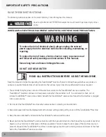
to reduce the risk of electrical shock, always unplug the external 

power supply from the electrical outlet before cleaning, maintaining, or 

repairing. 


to reduce the risk of burns, electric shock or injury to persons read 

and follow all safety warnings and instructions in this manual. 


secure long hair and loose clothing before use.  

do not use near water!

7 ! 2 . ) . '

! 4 4 % . 4 ) / .

$ ! . ' % 2

)--%$)!4%!#4)/.2%15)2%$

# ! 5 4 ) / .

7 ! 2 . ) . '

! 4 4 % . 4 ) / .

$ ! . ' % 2

)--%$)!4%!#4)/.2%15)2%$

# ! 5 4 ) / .

Summary of Contents for Commercial Series TreadClimber TC916

Page 1: ...Be Strong P n 001 7013 rev b 11 09 2006 assembly manual TreadClimber Model TC916 Commercial Series...

Page 2: ...For detailed instructions and information on how to use and care for your treadclimber Commercial series exercise machine model tc916 refer to the owner s manual 4 4 4 2 4 4 2 15 2 5 4...

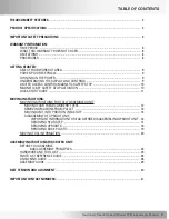
Page 3: ...y Stop Activation 10 Quick start guide 11 Moving instructions Moving instructions for fully assembled unit Moving Your treadclimber tc916 12 Removing machine from pallet 13 Moving unit into position i...

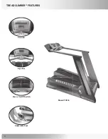
Page 4: ...4 TReaDclIMbeR feaTURes console ergo bar Power on off switch adjustable feet Model Tc916...

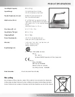
Page 5: ...806 lbs 366 kg Power Requirements USA 110 Volt 20 amp dedicated circuit International 230V 10 amp dedicated circuit Warranty 3 years parts 1 year labor 1 year wear items and 15 years frame and AC moto...

Page 6: ...ged into a power source 2 Do not start the TreadClimber machine when someone else is standing on the walk belts 3 Keep walk speed and treadle displacement at the lowest settings when getting on and of...

Page 7: ...not stand on the TreadClimber TC916 s hood or front trim cover 13 Close supervision is necessary whenever the machine is used by or near children invalids or disabled persons Failure to follow the co...

Page 8: ...vent be liable for incidental or consequential losses damages or expenses in connection with its exercise products Nautilus liability hereunder is expressly limited to the replacement of goods not com...

Page 9: ...er is GFI look for a test and reset button on them If they have the test and reset button it is a GFI outlet or circuit breaker and therefore not suitable for plugging the TreadClimber machine into Po...

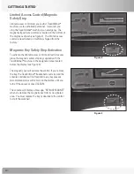
Page 10: ...he limited access control and restrict access place the magnetic safety stop key supplied with the TreadClimber machine in the designated area located below the display see Figure 3 The magnetic key w...

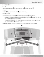
Page 11: ...umeric keypad to enter information Walk speed may be changed at any time during the workout by pressing the Speed UP key to increase the walk speed or the Speed DOWN key to decrease the walk speed Tre...

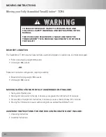
Page 12: ...facility if door ways are greater than 40 inches 101 cm wide 3 Disassembly of Upright Unit Instructions if door ways are less than 40 inches 101 cm wide 4 Moving Tool Information to assist with movin...

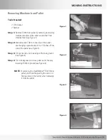
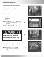
Page 13: ...ne side of the pallet over hanging approximately 12 to 15 inches off the side of the pallet see Figure 2 Step 3 Tilt unit to side and slide edge of frame to ground see Figure 3 Step 4 Tilt to 40 degre...

Page 14: ...onto 4 wheel moving dolly see Figure 3 Step 4 Once in position in the facility prepare to remove unit from 4 wheel dolly by locking castors MOVING instructions Moving Unit into Position in Facility Fi...

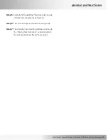
Page 15: ...ully tilt TreadClimber machine onto one side of frame towards ground see Figure 4 Step 6 Tilt unit to 40 degrees and remove moving dolly Step 7 Place Moving Tool under the machine according to the Mov...

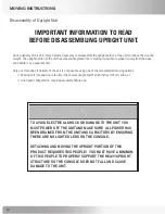
Page 16: ...ons Moving unit into position in facility if door ways are greater than 40 inches 101 cm wide or One boxed configuration requiring assembly before use To avoid electrical shock or damage to the unit y...

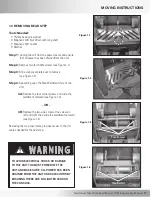
Page 17: ...1 2 Step 4 Depending upon the Step Weldment style of the unit 4A Remove the four corner screws and slide the weldment outward see Figure 1 3 OR 4B Remove the two side screws One screw on left and rig...

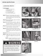
Page 18: ...2 4 Step 5 Remove right and left lower plastic parts by removing seven 7 screws located on the right and left upright inside panels see Figure 2 5 and Figure 2 6 Step 6 Remove the four 4 upright bolts...

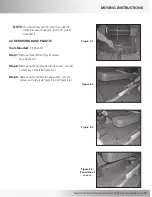
Page 19: ...ransport it 3 0 Removing Base Plastic Tools Needed 1 8 Allen bit Step 1 Remove three 3 front plastic screws see Figure 3 1 Step 2 Remove right and left side plastic covers four 4 screws each side see...

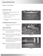
Page 20: ...and brace with a 4x4x6 inch ca 10x10x15 5 cm block of wood near the middle of the machine Step 2 Lift the left side of the TC916 and brace with a 4x4x6 inch ca 10x10x15 5 cm block of wood near the mi...

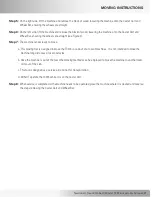
Page 21: ...The machine is now ready to move a This moving tool is designed to move the TC916 in and out of a row of machines It is not intended to move the machine long distances or over obstacles b Once the mac...

Page 22: ...ning toward the right will tighten turning towards the left will loosen An easy way to remember this is by remembering the expression Lefty loosey righty tighty 3 Gather all of the tools needed for as...

Page 23: ...Part Number 17683 Qty 8 Descr Internal External Washer 375 Part Number 17775 007 Qty 4 Descr Washer 50 SAE Flat Part Number 22091 Qty 4 Descr Washer Split Lock 50 Part Number 22222 Qty 4 Descr Screw 1...

Page 24: ...Number 17919 NOT ILLUSTRATED Qty 1 Descr Assembly Owner s Manual Kit and Hardware Kit Bag Qty 1 Descr Left Upright Plastic Cover Part Number 17669 Qty 1 Descr Right Upright Plastic Cover Part Number 1...

Page 25: ...y Manual Assembly instructions Qty 1 Descr TC916 TreadClimber Base Assembly Part Number 17500 Qty 1 Descr TC916 TreadClimber Handrail Assembly Part Number 17793 Qty 1 Descr TC916 TreadClimber Handrail...

Page 26: ...el TC916 Step 1 Opening Crate Tools Scissors or utility knife 1 1 Remove the outer cardboard to reveal the contents of crate Step 2 Unpacking Crate Tools Scissors or utility knife 2 1 Remove the three...

Page 27: ...vers Marked Long Side Panels on the box Box 1B Console Marked Control Panel on the box Rear Step weldment see Figure 1 Hardware Bag containing TV Cable if applicable Owners Manual Magnet Cord Clamp Gr...

Page 28: ...by removing restraining stabilizer brackets with socket and ratchet from stabilizer feet see Figure 1 5 2 Manually slide TC916 to one side of the pallet over hanging approximately 12 to 15 inches off...

Page 29: ...ing for this step Parts Base Assembly P N 17500 Handrail Upright Support Assembly P N 17794 1 1 Locate the three Ground Wire Straps on either side of the Base Assembly making sure that the wire is ext...

Page 30: ...g careful not to pinch wiring harness See Figure 2 and Figure 2A 2 2 Repeat Step 2 1 on the left side 2 3 Using the drive ratchet tighten the 2 lower bolts on each side first and then the 2 upper bolt...

Page 31: ...nd of grounding strap to the cross bar of the lower Upright weldment with a screw and lock washer See Figure 3 Grounding Strap 1 3 4 Attach one end of second grounding strap to the left side of base f...

Page 32: ...24 from the Handrail Upright Support Assembly P N 17794 to the Handrail Assembly See Figure 4 NOTE Carefully slide the Upper Upright Cables TV Cable if applicable inside Handrail Upright Support Assem...

Page 33: ...rews P N 25796 8 washers P N 17775 007 Tools 7 32 Allen bit 5 1 Bolt Handrail Assembly P N 17793 to Handrail Upright Support Assembly P N 17794 using 8 screws and 8 washers See Figure 5 IMPORTANT Make...

Page 34: ...to Console P N 17670 on the left and right side See Figure 6 NOTE If TV Cable present connect to mating cable from the console 6 2 Being careful not to pinch the wiring harness slide the console into...

Page 35: ...rs Locate the following for this step Parts Assembly from Step 7 Right Bottom Plastic Pivot Cover P N 17919 Left Bottom Plastic Pivot Cover P N 17918 Hardware 14 screws P N 17815 14 washers P N 17578...

Page 36: ...P N 17815 6 washers P N 17578 Tools Phillips screw driver 9 1 Attach the Rear Motor Cover using 6 screws and 6 washers See Figure 9 IMPORTANT Make sure that free end of grounding strap installed in s...

Page 37: ...22637 NOTE Due to the tight spacing a magnetic tool is recommended during this step 10 2 Secure the loose end of third grounding cable that was installed in Step 3 to the Step weldment on the left sid...

Page 38: ...17815 and 8 washers P N 17578 See Figure 10 11 2 Repeat Step 11 1 on the left side of the unit Assembly instructions Figure 11 Attaching Upright Plastic Covers Right Upright Plastic Cover Left Upright...

Page 39: ...loose uncovered or unattached parts prior to use 7 2 2 Failure to visually check and test assembly before use can cause damage to the Nautilus TreadClimber Model TC916 exercise machine and serious inj...

Page 40: ...ipping during use Excessive belt tension will decrease belt life and can damage the TreadClimber rollers and drive system Tools Needed 5 16 Allen wrench Belt alignment and tensioning adjustments see F...

Page 41: ...he appropriate Nautilus office listed below For technical assistance and a list of distributors in your area please call or fax one of the following numbers INTERNATIONAL CUSTOMER SERVICE internationa...

Page 42: ...42 Page Intentionally Left Blank...

Page 43: ...43 Nautilus TreadClimber Model TC916 Assembly Manual Page Intentionally Left Blank...

Page 44: ...ilus the Nautilus logo TreadClimber and Be Strong are either registered trademarks or trademarks of Nautilus Inc Nautilus Inc World Headquarters 16400 SE Nautilus Drive Vancouver Washington USA 98683...

Reviews: