Nautel XR12 Operation And Maintenance Manual Download Page 30

XR12 Operations and Maintenance Manual

Operating the transmitter

Issue 3.1   2013-03-14

Page 2-5

Using GUI pages

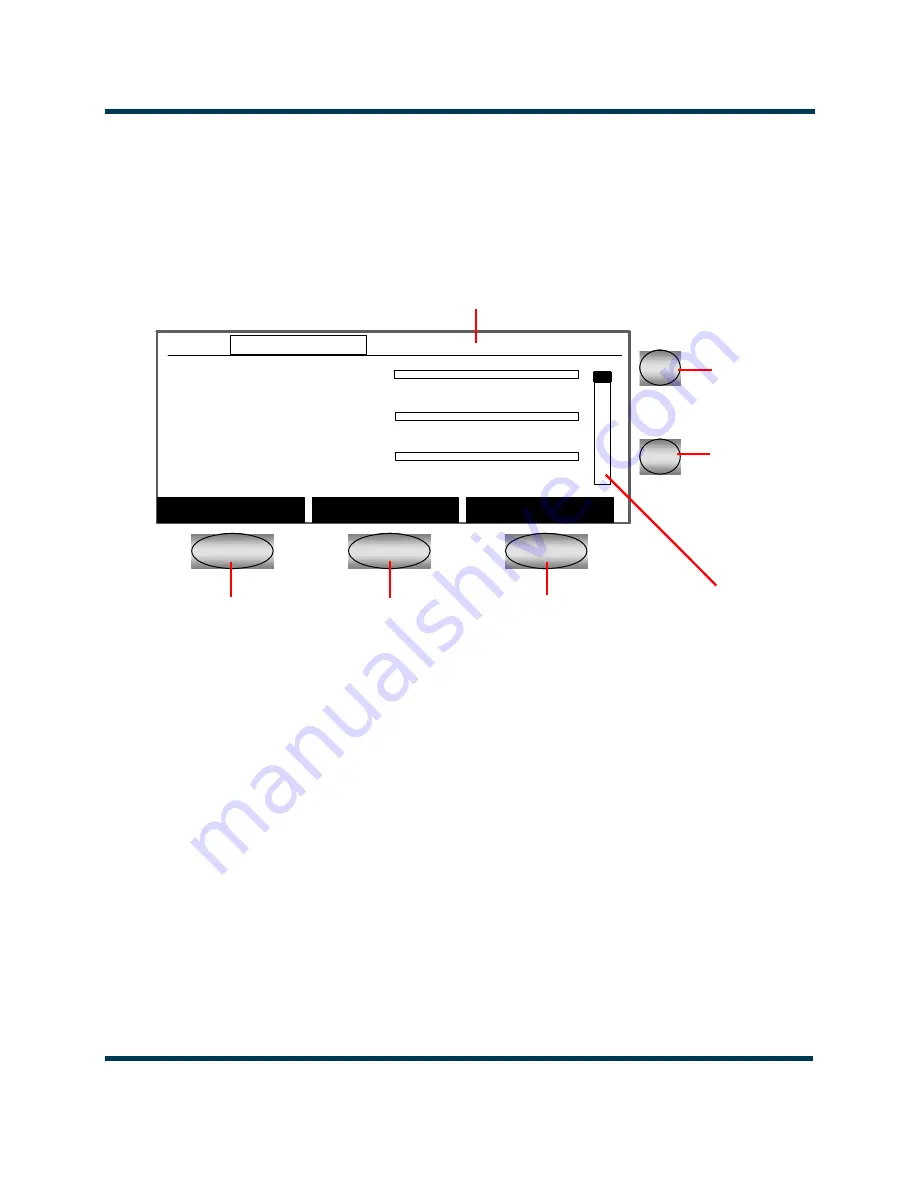
Each GUI page provides information about a specific transmitter function. The status bar at the top 
of every page shows the time, the current power, the Preset Scheduler status (M for manual or A for 
automatic), the current preset number, the active power modules, the power module transfer function 
status, the active exciter, and the exciter transfer function status.

Five buttons, called 

soft keys

, appear below and to the right of the GUI screen. These buttons let you 

scroll through information, move from page to page, and change settings. The actions that take place 
when you press 

Soft Key 1

2

, or 

3

 are shown in the black labels on the screen directly above each soft 

key (e.g., 

Edit

 or 

Back

).

Viewing information. 

When you move to a new GUI page, the page is displayed in the 

Select 

mode. In the 

Select

 mode, press the desired 

Soft Keys

 to move the cursor (the selected area of the 

screen), and scroll through lists or menus. You can use the 

Up

 and 

Down

 buttons to scroll through 

information on any page that has a vertical scroll bar. 

Editing settings. 

In screens where you can edit information, use the 

Up

 and 

Down

 buttons to 

move the cursor and highlight the information you wish to change, then press 

Soft Key 2

 (the 

Edit


button) to enter 

Edit

 mode. After editing the information, press the 

Save

 button


to save the changes, 

or the 

Cancel

 button to discard your changes, and return to the 

Select

 mode.

Soft Key 1

Soft Key 2

Soft Key 3

Up

Down

Forward Power:0.00W

0

5

10

Reflec. Power:  0W

0

500

1000

Total DC Curr: 0.0A

0

25

50

Menu

Status

Preset

10:18  0.00kW M-1 B+1 PM:A  Man Ex:A Man

n

n

n

5

6

Forward Power:0.00W

0

5

10

Reflec. Power:  0W

0

500

1000

Total DC Curr: 0.0A

0

25

50

Menu

Status

Preset

10:18  0.00kW M-1 B+1 PM:A  Man Ex:A Man

Forward Power:0.00W

0

5

10

Reflec. Power:  0W

0

500

1000

Total DC Curr: 0.0A

0

25

50

Menu

Status

Preset

10:18  0.00kW M-1 B+1 PM:A  Man Ex:A Man

n

n

n

5

6

Status Bar

Scroll Bar

Summary of Contents for XR12

Page 1: ...XR12 Transmitter Operations and Maintenance Manual Document NHB XR12 OPS Issue 3 1 2013 03 14 Status Standard...

Page 2: ...left blank intentionally...

Page 3: ...cle Bangor Maine USA 04401 Phone 1 207 947 8200 Fax 1 207 947 3693 Email support nautel com Web www nautel com The comparisons and other information provided in this document have been prepared in goo...

Page 4: ...left blank intentionally...

Page 5: ...ds 3 xii Safety Precautions xiii Personal Safety 3 xiii Site Safety 3 xiv Equipment Safety 3 xvi Description 1 1 Ac dc power stage 1 1 Exciter stage 1 2 RF power stage 1 4 RF output filter 1 5 Control...

Page 6: ...the event log 3 1 Viewing the event log 3 1 Clearing the event log 3 6 Event log messages 3 7 Routine maintenance 4 1 Scheduled maintenance 4 1 Replacing air filter 4 2 Performing on air checks 4 3 R...

Page 7: ...d during a troubleshooting task see Section 5 Test and adjustment on page 5 1 Performing procedures When using procedures in this manual perform each step in sequence If you are asked to see another s...

Page 8: ...warranty information see Pre installation assistance on page 11 1 of the XR12 Pre Installation Manual For extended warranty information see Pre installation assistance on page 11 1 of the XR12 Pre In...

Page 9: ...UG The website includes a special section that customers can log into in order to access the Nautel customer newsletter product manuals frequently asked questions FAQ information sheets and informatio...

Page 10: ...XR12 Operations and Maintenance Manual Page x Issue 3 1 2013 03 14...

Page 11: ...ess of 72 volts capable of causing a fatal electrical shock are present on or near parts bearing this label Mount the transmitter ac power disconnect switch breaker close to the transmitter so that it...

Page 12: ...ese devices are specifically identified with BeO in the Description column of the Troubleshooting Manual s parts list s Do not cut crush or grind devices because the resulting dust may be hazardous if...

Page 13: ...ber of training courses covering the basic fundamentals of RF systems and transmitters and the operation and maintenance of the transmitter For more information about available courses and schedules g...

Page 14: ...Nautel does not offer first aid training since the hazards associated with high voltage and RF energy are not specific to the transmitter However the customer should provide first aid training to all...

Page 15: ...larly near the feedline antenna and tower At some sites these fields may cause biological effects including the heating of body tissues Intense fields can also create dangerous high voltages on ungrou...

Page 16: ...g any exposed components Provide a grounding wand or known ground e g a grounded metal table that personnel can use to discharge themselves Surge Protection Surge protection is recommended for your en...

Page 17: ...Do not place the transmitter under water pipes drains or sprinklers Keep any equipment that generates heat like the transmitter away from flammable materials like ceiling panels cubicle dividers and...

Page 18: ...XR12 OPERATIONS AND MAINTENANCE MANUAL PAGE XVIII VERSION 3 1 2013 03 14...

Page 19: ...end of the XR12 Troubleshooting Manual Redundancy The XR12 features redundancy in all key systems RF power modules optional fully redundant backup is available Exciters Cooling fans Ac dc power stage...

Page 20: ...Bs A A2A3 and B A2A5 distribution PWB A16 and RF drive buffer PWB A24 The exciter stage contains two independent exciter sections A and B which can be selected automatically or by local or remote cont...

Page 21: ...A and Fc B The Fc A and Fc B signals are provided to the RF drive buffer PWB via the exciter interface PWB The RF synthesizer PWBs also provide signals at twice the pulse duration switching frequency...

Page 22: ...set input provides a reset pulse to reset protection circuits internal to the interphase PDM driver PWB RF drive buffer PWB The RF drive buffer PWB A24 buffers the carrier frequency signal Fc generate...

Page 23: ...ree RF power modules Each RF power module has two parallel inductors in the combiner RF Power Module 1 RF 1 A Spark Gap Shutback A4 Forward Reflected Power Probe RF Sample Forward Power Sample Reflect...

Page 24: ...monitoring and RF power stage status information is applied to the control monitor stage Based on the value and status of each input the control monitor stage produces the appropriate control signals...

Page 25: ...ERFACE EXCITER STAGE PWB REMOTE PWB BUFFER INTERFACE ETHERNET PWB DISTRIBUTION B P S AC DC RF POWER RF POWER STAGE PDM DRIVER PDM DRIVER INTERPHASE RF PWB A PWB EXCITER INTERFACE RF DRIVE MODULE OPTIO...

Page 26: ...Scheduler mode see page 2 9 Changing general settings see page 2 10 Controlling presets see page 2 10 Changing power preset schedules see page 2 12 Changing meter groups see page 2 13 Viewing digital...

Page 27: ...UI provides soft menus that change depending on the information screen being displayed and the transmitter s status CHECKSUM error screen 1 In the unlikely event that the CHECKSUM error screen appears...

Page 28: ...nge the hardware settings press the Continue button to proceed Otherwise press the Back button to return to the Main Menu page GUI pages Table 2 1 defines the available GUI pages Table 2 1 GUI Pages G...

Page 29: ...esholds Calibrate Meters Calibrate Analog Meters and Factory Settings pages page 2 21 Calibrate Meters Calibrate the digital meters available in the GUI page 2 24 Set Thresholds Change the thresholds...

Page 30: ...elect mode press the desired Soft Keys to move the cursor the selected area of the screen and scroll through lists or menus You can use the Up and Down buttons to scroll through information on any pag...

Page 31: ...power modules on page 2 8 Select Automation control to change the settings for auto exciter switchover and the power scheduler see Changing automation settings on page 2 9 Select Software version to v...

Page 32: ...ctive cutbacks and reduce the estimated soft start relay temperature to 150 C 302 F if it is over that temperature Press the Back button to return to the Meters page Note The software keeps track of t...

Page 33: ...sible combinations are Modules A and B enabled with module C on standby Modules A and C enabled with module B on standby Modules B and C enabled with module A on standby The Current Status line displa...

Page 34: ...mode value and pressing the Edit button You can then use the Up or Down buttons to change the setting to Manual or Auto Auto Scheduler mode In Auto Scheduler mode the scheduler controls which preset i...

Page 35: ...rolling presets see page 2 10 Changing meter groups see page 2 13 Adjusting screen contrast see page 2 20 Changing hardware settings see page 2 20 Press the Back button to return to the Main Menu see...

Page 36: ...wer monitor gain or main power module Then press the Edit button to alter the selected setting Your changes take effect immediately For example if you change the RF power monitor gain the RF power mon...

Page 37: ...mpanied by an animated arrow and the text Different indicating that there is a difference between the active power level and the preset s stored power level Press the Set Power button to store the cur...

Page 38: ...rt time for the preset The time is in 24 hour format For example 06 00 is 6 a m and 18 00 is 6 p m Press the Clear button if you want to remove the preset from the schedule The time will appear as and...

Page 39: ...the Back button to return to the General Settings menu Viewing digital meters You can use the GUI to view digital meters meter scales shown on the GUI screen The Meters page displays up to 12 differe...

Page 40: ...ress the Up or Down buttons to scroll to different meters Press the Menu button to go to the Main Menu If an alarm is active a Status button appears Press the Status button to go to the Status page Pr...

Page 41: ...the cursor over the fields from left to right to highlight a value To change the highlighted value press the Edit button then press the Up or Down button to increase or decrease the value Press the S...

Page 42: ...r a 30 day period for the previously set value of Current RTC Calibration Delta 30 day Correction Displays the difference between the Previous 30 day Correction and the Effective 30 day Correction to...

Page 43: ...f the XR12 s clock lost time on the standard the Delta 30 day Correction value should be positive 4 Press the Save button to store the calibration value 5 Reset the XR12 s clock according to the time...

Page 44: ...age shows the release number and the date of the release The right side of the page shows information about the individual components in the current release Press the Refresh button to update the valu...

Page 45: ...the setting Changing hardware settings You can set thresholds calibrate digital and analog meters and restore factory settings using the Hardware Settings menu To view the Hardware Settings menu sele...

Page 46: ...nk optional see page 2 29 Press the Back button to return to the General Settings menu If you select Factory Settings a warning screen appears Press the Continue button to move to the Factory Settings...

Page 47: ...current shutback circuitry Maximum Carrier Reference Limits the maximum allowable carrier reference signal Minimum Carrier Reference Limits the minimum allowable carrier reference signal B Reconnect L...

Page 48: ...If the transmitter is ramping up to a power level that is less than the maximum carrier reference the ramp up time will be less than the interval setting To change a threshold select the threshold and...

Page 49: ...nd after the change for future reference Calibrating analog meter You can recalibrate the XR12 s analog forward power meter if necessary using the Calibrate Analog Meter page Note The transmitter is c...

Page 50: ...as the full scale meter indication Press the Save button to save your calibration 3 Use the Up and Down buttons to select Half Scale Meter Reading Press the Edit button then press the Up and Down butt...

Page 51: ...lue to the same value as the Current Carrier Reference Press the Save button to save your setting Pressing the Cancel button discards your changes 4 Use the Up and Down buttons to select High Power Lo...

Page 52: ...pears asking you to confirm that you wish to proceed Figure 2 22 Factory Settings warning page Note The Factory Settings menu is available only when operating in Local mode 10 18 0 00kW M 1 PM AB Man...

Page 53: ...perating the transmitter Page 2 28 Issue 3 1 2013 03 14 Press the Cancel button to cancel the request leaving your transmitter settings intact or press the Confirm button to restore the factory settin...

Page 54: ...ns to select IP Address Netmask Gateway or DNS Server DHCP d Address is not a selectable field The address is automatically assigned when the NxLink is connected to a LAN if DHCP is available on the n...

Page 55: ...XR12 Operations and Maintenance Manual Operating the transmitter Page 2 30 Issue 3 1 2013 03 14...

Page 56: ...page The Events Log page shows a list of recent faults and other events The second line of the page shows the total number of events in the log the number of alarms and the index number of the event...

Page 57: ...able event pages An indicator appears in the bottom right corner of the page showing the page number and the total number of available event pages Press the Next Event button to view the next event in...

Page 58: ...an 001 24Oct06 10 48 43 LVPS Fault RF Power Off Fwd Power 0 00kW Control Local Shutback Yes Exciter A Man Cutback 0 PM AB Man Preset M 1 Use Up Dn Keys to view event data 1 5 Next Event Back 10 18 0 0...

Page 59: ...0 0V PA Volt P S 0 0V 15 Volt P S 0 0V RF Drive P S 0 0V 15 Volt P S 0 0V Fan P S 0 0V 5 Volt P S 0 00V Use Up Dn Keys to view event data 3 5 Next Event Back 10 18 0 00kW M 1 PM AB Man Ex A Man 001 24...

Page 60: ...nt Page 5 10 18 0 00kW M 1 PM AB Man Ex A Man 001 24Oct06 10 48 43 LVPS Fault LVPS Fault Cutback Level 0 Use Up Dn Keys to view event data 5 5 Next Event Back 10 18 0 00kW M 1 PM AB Man Ex A Man 001 2...

Page 61: ...tents of the Events Log press the Clear Log button A warning screen will appear Figure 3 7 Clear Log Warning page Press the Continue button to clear the log or press the Back button to return to the M...

Page 62: ...Preset changes using the Preset Scheduler have been disabled Command Exciter A Changeover to Exciter A Command Exciter B Changeover to Exciter B Command LOCAL Remote control has been disabled Local co...

Page 63: ...XR12 Operations and Maintenance Manual Using the event log Page 3 8 Issue 3 1 2013 03 14...

Page 64: ...sits is three months Local operating and environmental conditions may dictate more frequent visits while in remote sites less frequent visits may be acceptable Experience and system reliability will d...

Page 65: ...backup circuit that provides a memory of alarm occurrences during ac power failure See Replacing the control display PWB battery on page 4 3 Replacing air filter In order to maintain your transmitter...

Page 66: ...smitter A spectrum analyzer if one is available Procedure 1 Monitor the transmitter signal to identify any problems Use a high quality receiver to monitor audio quality Check the spectral output of th...

Page 67: ...k for any alarms on the graphic user interface See Viewing alarm status on page 2 7 Inspecting lightning protection systems You should inspect the lightning protection systems that are connected to yo...

Page 68: ...inspect the lightning arrestor to ensure that all connections are tight Also look for any sign of scoring or burning indications of possible damage from earlier lightning strikes 3 Using binoculars v...

Page 69: ...XR12 Operations and Maintenance Manual Routine maintenance Page 4 6 Issue 3 1 2013 03 14...

Page 70: ...act a specific adjustment can have on other steps These adjustments should be performed during initial turn on and after major repairs or a frequency change Test equipment required To perform the proc...

Page 71: ...checks Verify that the RF output is appropriately modulated when audio is applied 1 Connect an appropriate modulation monitor to the remote interface PWB RF MONITOR connector J8 The modulation monito...

Page 72: ...is required it is recommended the AUDIO GAIN potentiometer on the interphase PDM driver PWBs be left at the factory setting 8 If the program audio cannot be set to 10 dBm when 100 modulation is requi...

Page 73: ...xciter A as the active exciter 2 Connect an oscilloscope to BNC connector J5 RF DRIVE TEST on the RF drive buffer PWB 3 The oscilloscope should indicate a symmetrical 50 duty cycle square wave with a...

Page 74: ...frequency long duration high amplitude peaks Verify the modulation peaks are limited as follows 1 Connect an oscilloscope between TP7 and ground on the remote interface PWB 2 Connect an audio signal...

Page 75: ...XR12 Operations and Maintenance Manual Test and adjustment Page 5 6 Issue 3 1 2013 03 14 Figure 5 1 Chopper Control Waveform Audio 30Hz AC Coupled...

Page 76: ...na B The high voltage dc generated by the transmitter s ac power supply for use within the transmitter The B voltage is used to supply the transmitter s modulators and other transmitter circuitry Cutb...

Page 77: ...ix presets Shutback A complete loss of RF output power caused by any one of a variety of faults including high VSWR low B voltage high RF current RF drive failure external interlock or spark gap Surge...

Page 78: ...2 9 Changing hardware settings 2 20 Changing meter groups 2 13 Checking hardware 4 2 Checks on air 4 3 Checksum error 2 2 Cleaning 4 1 Clearing the event log 3 6 Clock setting 2 16 Control monitor sta...

Page 79: ...ory settings 2 25 RF drive buffer PWB functional description 1 4 RF drive symmetry 5 4 RF Output Filter 1 5 RF Output Filter block diagram 1 5 RF output filter functional description 1 5 RF power bloc...

Page 80: ......

Page 81: ...877 6NAUTEL 662 8835 Canada USA only or Phone 1 902 823 3900 or Fax 1 902 823 3183 Nautel Inc 201 Target Industrial Circle Bangor Maine USA 04401 Phone 1 207 947 8200 Fax 1 207 947 3693 Customer Serv...

Reviews: