background image

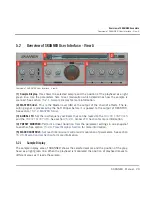
The first two macro controls (

SOURCE

VARIATION

) are designated to parameters of the syn­

thesis  engine  of  SKANNER  while  the  second  two  macro  controls  (

FILTER

SPACE

)  are  as­

signed to the three effects. These can be assigned to MIDI sources for example, a modulation 
wheel, or expression pedal. They can also be controlled by sequencer automation parameters 
within your DAW (Digital Audio Workstation).
When the 

LFO

 button below a Macro Control knob is clicked (lit) the knob becomes inactive 

and is replaced by the signal of the Global LFO. The modulation provided by the Global LFO is 
then represented by the animation of the outer ring of the knob.

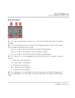
Macro Control Parameters

View A — Macro Controls section

[1] 

SOURCE

: Macro Control with up to three destinations in the sample reader engine. Typical­

ly for more "drastic" sound changes.
[2] 

LFO

: Activates the Global LFO to control the destinations of the 

SOURCE

 Macro Control.

[3] 

VARIATION

: Macro Control with up to three destinations in the sample reader engine. Typi­

cally for more subtle sound changes.
[4] 

LFO

: Activates the Global LFO to control the destinations of the 

VARIATION

 Macro Control.

[5] 

FILTER

: Macro Controller with up to two destinations in the 8-pole Filter.

[6] 

LFO

: Activates the Global LFO to control the destinations of the 

FILTER

 Macro Control.

[7] 

SPACE

: Macro Controller with up to two destinations in the Echo and Reverb effects.

[8] 

LFO

: Activates the Global LFO to control the destinations of the 

SPACE

 Macro Control.

Overview of SKANNER Ensemble

Overview of SKANNER User Interface - View A


SKANNER - Manual - 26

Summary of Contents for Skanner

Page 1: ...Manual...

Page 2: ...nd associated logos are registered trademarks of Native Instru ments GmbH Mac Mac OS GarageBand Logic iTunes and iPod are registered trademarks of Apple Inc registered in the U S and other countries W...

Page 3: ...e Str 29 30 D 10997 Berlin Germany www native instruments de USA Native Instruments North America Inc 6725 Sunset Boulevard 5th Floor Los Angeles CA 90028 USA www native instruments com Native Instrum...

Page 4: ...oading a Snapshot from the Main Bar 15 4 3 Saving a Snapshot 15 4 4 Selecting SKANNER A and B Panel Views 16 5 Overview of SKANNER Ensemble 18 5 1 Overview of Signal Flow 19 5 2 Overview of SKANNER Us...

Page 5: ...on 39 5 6 4 Miscellaneous Controls 40 5 7 Modulators Section 40 5 7 1 Oscillators A and B Sections 42 5 7 2 ENV Section 44 5 7 3 FDBK Section 45 5 7 4 LFO Section 46 5 8 Macro Controls Section 48 5 8...

Page 6: ...ither with the free REAKTOR PLAYER or the full version of REAKTOR 5 6 2 On behalf of the entire NA TIVE INSTRUMENTS team we hope this product will inspire you To get the best from this instrument plea...

Page 7: ...where labels of buttons controls text next to checkboxes etc is printed in light blue Whenever you see this formatting applied you will find the same text appearing somewhere on the screen Important n...

Page 8: ...complex synthesis going on under the hood SKANNER couldn t be easier to use Two views offer different levels of interaction The A view features four macro controls that are mapped to multiple paramete...

Page 9: ...When installation is finished start the Service Center application which was installed with SKANNER It will connect your computer to the Internet and activate your SKANNER installa tion In order to ac...

Page 10: ...l available updates for your installed prod ucts Please make sure that you always use the latest version of your Native Instruments prod ucts to ensure they function correctly Downloading updates is o...

Page 11: ...information on REAKTOR PLAYER files please refer to the REAKTOR 5 6 2 Get ting Started Guide 4 1 How to Open SKANNER This is how to open SKANNER in REAKTOR or REAKTOR PLAYER 1 Start REAKTOR or REAKTO...

Page 12: ...kanner folder The folder s content will be displayed in the lower section of the browser 4 Double click the Skanner ens file or drag it into the main screen How to Use SKANNER How to Open SKANNER SKAN...

Page 13: ...erent Snapshot A Snapshot is REAKTOR s notion for a sound preset or patch SKANNER can hold banks of Snapshots and loading any of these Snapshots will set each control of that Instrument to a specific...

Page 14: ...SKANNER interface with Snapshot list in the Sidepane 1 Sidepane Button 2 Snapshot drop down menu 3 Snapshot Banks 4 Snapshots How to Use SKANNER Exploring Factory set Snapshots SKANNER Manual 14...

Page 15: ...p down menu in the Main Bar is the sim plest way to interact with Snapshots 1 Click the Snapshot drop down menu control 2 The menu holds all Snapshots and Banks of the instrument 2 Click an entry to s...

Page 16: ...on the A View and B View buttons in the Instrument Header or by right clicking on the Instrument Panel and clicking on the View B or View A menu entry The A View and B View buttons in the Instrument...

Page 17: ...View B SKANNER View B How to Use SKANNER Selecting SKANNER A and B Panel Views SKANNER Manual 17...

Page 18: ...read gets into the audio range and domi nates the perceived pitch If only a part of the sample is read by the oscillator the position and width of this part deter mines the waveform of the output sign...

Page 19: ...position signal for the Sample Lookup module is gener ated and how the output of the sample reader is processed For a detailed description of all parameters please refer to 5 3 Overview of SKANNER Use...

Page 20: ...equency oscillator that can be routed to the MACRO CONTROLS and the PRESET MORPHER See section 5 2 3 Global LFO Section for more information 4 PRESET MORPHER Perform a linear transition from the param...

Page 21: ...e output of REAKTOR 5 2 3 Global LFO Section This LFO is separate from the polyphonic LFO in View B It can be routed to the four MACRO CONTROLS and to the position of the Preset Morphing It is a monop...

Page 22: ...The SHAPE knob in the far right position will create a rising sawtooth 3 PHASE When SYNC is on this parameter shifts the phase of the LFO in relation to the song position 1 falling ramp on the beat gr...

Page 23: ...form a linear transition from the setting in the first snapshot to the setting in the second snapshot A morph can be stopped at any point and can be reversed or modulated by other movements However th...

Page 24: ...t segment 3 POSITION This knob controls the morph position between the orange current snapshot segment at the far left end of the knob and the green target snapshot segment to the right end The morph...

Page 25: ...selections are swapped and if it is not running the morph will be started Clicking on another orange field will create a new pair for morphing the former green seg ment becomes orange highlighted and...

Page 26: ...acro Controls section 1 SOURCE Macro Control with up to three destinations in the sample reader engine Typical ly for more drastic sound changes 2 LFO Activates the Global LFO to control the destinati...

Page 27: ...ls to a MIDI controller like an expression pedal or to a sequencer automation parameter 5 3 Overview of SKANNER User Interface View B View B Overview Overview of SKANNER Ensemble Overview of SKANNER U...

Page 28: ...the position of the playhead as a light green line When the playhead is modulated the position of playhead moves to different areas as it reads the sample In the full version of REAKTOR a WAV or AIFF...

Page 29: ...back in its original pitch The sample display has a scrollbar and zoom in out buttons at its bottom The zooming and the scroll position are independent from the range and position of the sliders Synt...

Page 30: ...PLE Select one of eleven samples for the basis of your sound Sample slot 12 is free and can be used for your own samples if you are using the full version of REAKTOR You can also replace the first ele...

Page 31: ...Provides the option to multiply the sample reader output signal by a signal coming from the oscillators For detailed parameter descriptions see 5 5 1 AM Amplitude Modula tion 2 DELAY This is a polypho...

Page 32: ...modulation signal This works similar to a rectifier and creates second and other even harmonics When the oscillators run in sawtooth mode the amplitude is also modulated by a synchronous window in or...

Page 33: ...RY AM INPUT Mix amount of the amplitude modulated signal in the signal path to the Delay 2 LFO LFO amount for the tuning of the Delay At negative values the LFO phase is inverted 3 ENV Set the amount...

Page 34: ...This means it can strongly influence the feedback behavior Its signal is also available for the output mix and will influence the sound when it is mixed in Filter Parameters View B Filter section of...

Page 35: ...ting sound Mix Parameters View B Mix section of the Polyphonic Processing engine 1 SAMPLE Mix level for the direct output of the Sample reader 2 AM Mix level for the output of the AM amplitude modulat...

Page 36: ...sed to create sounds that continue long after the note has been pressed 5 Envelope Display Provides a visual representation of the current envelope shape 6 V Influence of the key velocity on the peak...

Page 37: ...With a negative GAP value the pass bands of both filters are overlapping so that all frequencies can pass and the resonances em phasize the cutoff frequencies The difference between the reference cut...

Page 38: ...gh pass and low pass filters Echo Parameters View B Echo Effects section 1 SYNC Sets the adjustment of the mean delay time to tempo synced values 2 TIME Mean delay time As there can be an offset betwe...

Page 39: ...depth to your sound View B Echo is a tempo synchronizable Reverb Parameters 1 MIX Crossfades between the dry signal and the reverberation signal 2 SIZE The room size and reverb time are set here 3 LO...

Page 40: ...will never clip if the output volume slider of REAKTOR is not set to larger than 0 dB Since the Soft Clip stage is realized by a sine shaper the saturation only becomes noticeable with higher amounts...

Page 41: ...and Random waveforms which can be used to modulate various targets 6 Modulator Macro Control Switch The lower area of the B view can be switched to show the MODULATORS field containing the modulation...

Page 42: ...een Sine Triangle and Saw tooth The output signal going to the sample reader is controlled by an ADBDSR envelope per oscillator The phase modulation inputs of the oscillators give the possibility to d...

Page 43: ...g of the oscillator pitch It s the scaling factor between the key position of a received MIDI note relative to C3 60 and the pitch of the oscillator At 1 0 the pitch follows the equally tempered scale...

Page 44: ...s the Attack Decay and Release rates with the keyboard At 0 the rates are constant at 1 they are fully tracking with the frequency of the played note This gives the possibility to read the sample by t...

Page 45: ...odulation and for the phase modulation of the oscillators The source of the feedback signal is determined by the MIX knob This can be used to cross fade between the output signal of the filter MIX kno...

Page 46: ...SYM knob adjusts the symmetry and by this can bend the triangle to become a sawtooth or reduce the pulse width of the Pulse signal As a polyphonic unit it can be synced to note ons with adjustable st...

Page 47: ...SHAPE Use the SHAPE knob to crossfade between different waveforms of the LFO The values below produce the following results 0 Sine SHAPE knob in the far left position 1 Triangle 2 Pulse 3 Random SHAP...

Page 48: ...r controller targets can be set by the corresponding faders Sliding the fader to the right causes positive modulation sliding it to the left causes negative modula tion amounts This means that for pos...

Page 49: ...ations in the sample reader engine Typical ly this is used for more drastic sound changes Source Parameters View B Source parameters 1 SOURCE The Macro Control knob which is the source of modulation f...

Page 50: ...FB Pos FB Pos Fine Pos Coarse Pos Fine Feedback Int Ext Delay Tune Delay Tune AM A B Filter Lo Cut Filter Hi Cut Delay AM Mix Osc A Wave Osc A Wave Mixer Sample Osc B Wave Osc B Wave Mixer AM LFO Rat...

Page 51: ...e monophonic LFO Control amount of the Macro Controller on the first second and third target 3 Amount Sliders Control amount of the Macro Control on the first second and third target 4 LFO When this b...

Page 52: ...e FILTER macro control has three targets that can be chosen by drop down menus each with its own control level It is suggested to assign it to a MIDI con troller like an expression pedal or as a seque...

Page 53: ...or the target parame ters 2 Modulation Target Menus The SPACE macro control has three targets that can be chosen by drop down menus each with its own control level It is suggested to assign it to a MI...

Page 54: ...the Global LFO Space Modulation Targets Destination 1 Destination 2 Echo Time Echo Time Echo LR Offset Echo LR Offset Echo Feedback Echo Feedback Echo Mix Echo Mix Reverb Size Reverb Size Reverb Mix...

Page 55: ...es and Georg Haupt Product Design Stephan Schmitt and Efflam Le Bivic Graphic Design Gregory Pignot Efflam Le Bivic and G sta Wellmer Sound Design Robert Linke Jamil Samad Angelos Liaros Klaus Dieter...

Reviews: