NATIONAL HYDRO 70" TRIPLEX
®
13
6OPERATION
7ADJUSTMENTS
7.1ADJUSTMENTS
Read each instruction completely and
make sure you understand it before
making any adjustment. Follow all the
safety precautions.
To avoid possible serious bodily injury,
before making any adjustments or
performing maintenance, place all tractor
controls in Neutral, engage parking
brake, fully lower cutting units to the
ground, turn ignition switch Off and
remove key.
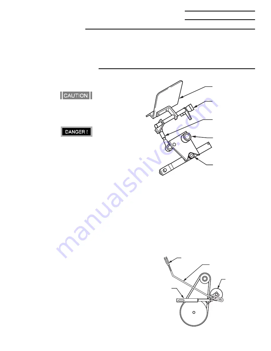
7.2TRACTION PEDAL
ADJUSTMENT
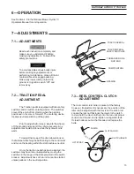
The Traction pedal is equipped with two safety
switches and a neutral centering device. The switches
prevent the engine from starting when the pedal is
positioned in reverse or forward. The centering device
locates neutral positioning of the pump.
Prior to adjusting for creep, elevate the wheels
off the ground and support the vehicle securely. Any
adjustments should be done while the hydraulic oil is
warm.
To adjust the creep of the drive wheels loosen
the fastener attaching the ball bearing to the control arm
and move the bearing within the slot to achieve neutral.
Once the traction pedal has been adjusted, the
switches may have to be re-adjusted by moving the
switches in the range of the slots provided in the switch
bracket. Adjust switches so that unit cannot be started
unless pedal is in the neutral position.
See Section 4.0 in the National Mower Hydro 70
Operators Manual for unit operation.
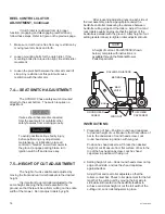
7.3REEL CONTROL CLUTCH
ADJUSTMENT
The reel control clutch idler is preset at the factory.
However, if adjustment is necessary, the position of the
idler can be adjusted with the clevis on the clutch rod.
Loosen the jam nut that locks the clevis to the clutch
rod and turn the clevis further onto the rod until proper
tension is achieved, and re-tighten nut against clevis.
If clevis bottoms out on the threaded rod replace the
belts.
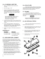
TRACTION PEDAL
TRACTION PEDAL
SAFETY SWITCHES
THREADED ROD &
ROD END
PUMP CONTROL
BEARING
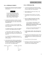
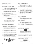
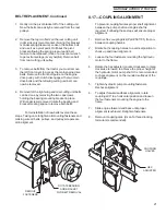
CLEVIS
CLUTCH ROD
CLUTCH IDLER
LIFT STRAP
Summary of Contents for HYDRO 70" TRIPLEX
Page 28: ...HY70OM 8 99 28 ...
Page 30: ...HY70OM 8 99 30 ...
Page 32: ...HY70OM 8 99 32 ...
Page 34: ...HY70OM 8 99 34 ...
Page 36: ...HY70OM 8 99 36 ...
Page 38: ...HY70OM 8 99 38 ...
Page 40: ...HY70OM 8 99 40 ...


