background image

©

 National Instruments Corporation

3

SCC-68 User Guide

Conventions

The following conventions are used in this manual:

<>

Angle brackets that contain numbers separated by an ellipsis represent 
a range of values associated with a bit or signal name—for example, 
AO <3..0>.

»

The 

»

 symbol leads you through nested menu items and dialog box options 

to a final action. The sequence 

File»Page Setup»Options

 directs you to 

pull down the 

File

 menu, select the 

Page Setup

 item, and select 

Options


from the last dialog box.

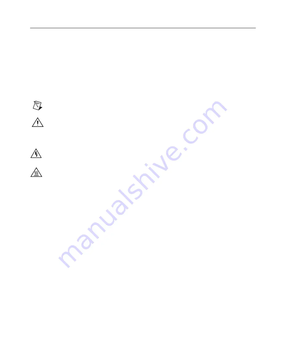
This icon denotes a note, which alerts you to important information.

This icon denotes a caution, which advises you of precautions to take to 
avoid injury, data loss, or a system crash.


When this symbol is marked on 

the product, refer to the 

Read Me First: Safety and Radio-Frequency 

Interference

 document, shipped with the product, for precautions to take.

When symbol is marked on a product, it denotes a warning advising you to 
take precautions to avoid electrical shock.

When symbol is marked on a product, it denotes a component that may be 
hot. Touching this component may result in bodily injury.

bold

Bold text denotes items that you must select or click in the software, such 
as menu items and dialog box options. Bold text also denotes parameter 
names.

italic

Italic text denotes variables, emphasis, a cross-reference, or an introduction 
to a key concept. Italic text also denotes text that is a placeholder for a word 
or value that you must supply.

monospace

Text in this font denotes text or characters that you should enter from the 
keyboard, sections of code, programming examples, and syntax examples. 
This font is also used for the proper names of disk drives, paths, directories, 
programs, subprograms, subroutines, device names, functions, operations, 
variables, filenames, and extensions.

SCC-

XX

This name refers to any SCC module.

Summary of Contents for SCC-68

Page 1: ...lay isolated digital I O and isolated voltage input SCC modules into the measurement system Contents Conventions 3 Using the SCC 68 Enclosure 4 Opening the Enclosure 4 Closing the Enclosure 5 Stacking...

Page 2: ...23 Differential 24 Single Ended 24 Non Referenced Single Ended NRSE 25 Grounded Signal Sources 25 Floating Signal Sources 26 Ground Referenced Single Ended RSE 26 Grounded Signal Sources 26 Floating S...

Page 3: ...ith the product for precautions to take When symbol is marked on a product it denotes a warning advising you to take precautions to avoid electrical shock When symbol is marked on a product it denotes...

Page 4: ...nclosure To open the SCC 68 use a flathead screwdriver to loosen the captive screw at the front of the device After the screw is loosened pull up on the front of the enclosure cover to open The top ha...

Page 5: ...head screwdriver to push the screw down against the spring resistance and tighten the screw Caution The captive screw must be used to secure the enclosure when connecting hazardous voltage 30 Vrms 42...

Page 6: ...8 also has mounting holes on the bottom of the device for secure wall mounting The third mounting hole allows you to mount the SCC 68 onto a wall sideways or inverted Refer to Figures 3 and 4 for more...

Page 7: ...skid feet are shipped with the device that can be attached for secure desktop use To install the rubber feet remove adhesive backing and affix to the SCC 68 where indicated in Figure 4 Figure 4 SCC 6...

Page 8: ...8 to the DAQ device using one of the following cables SHC68 68 EPM SHC68 68 RC68 68 3 Proceed to the Taking Measurements with NI DAQmx section for information about using the SCC 68 in measurement app...

Page 9: ...on for the quick reference guide for the SCC 68 connected to Connector 1 of the DAQ device The guide shows the pin assignments of the SCC 68 and other useful information Attach a copy of this guide to...

Page 10: ...68 Connector Block and Another Terminal Block You cannot use the Extended I O connector with an SCC 68 Use another terminal block such as the SCB 68 or CB 68LPR with the Extended I O connector 2 Refe...

Page 11: ...Relief Wire Entry SCC Mod 1 SCC Mod 2 SCC Mod 3 SCC Mod 4 ROUTE SCC SIGNAL WIRES ON THIS SIDE SCC Mod 1 SCC Mod 2 SCC Mod 3 SCC Mod 4 USE SCC CONNECTOR BACKSHELL FOR HAZARDOUS LIVE SIGNALS 42 4 Vpk 60...

Page 12: ...SCC 68 refer to the Integrated Strain Relief section 4 Connect the wires to the screw terminals by stripping off 7 mm 0 28 in of the insulation inserting the conductors into the terminals and tighteni...

Page 13: ...enuation For soldering components to the underside of the breadboard remove the printed circuit board by carefully snapping it loose from the SCC 68 enclosure To desolder on the SCC 68 vacuum type too...

Page 14: ...n compensation of thermocouple measurements connect CJC terminal 70 to AI channel 7 of the SCC 68 Figure 9 shows the temperature sensor connected to AI 7 Figure 9 Connecting the CJC Sensor to Channel...

Page 15: ...tween the screw terminals of the SCC 68 is typically less than 1 C Variations in the ambient temperature SCC module heat dissipation and heat conducted along thermocouple wire can all contribute to is...

Page 16: ...68 including the 5V screw terminal pin 8 The 5V power on the DAQ device is current limited For more information about the power supply and possible limitations refer to the Power Supply Considerations...

Page 17: ...s connected to the module Caution The captive screw must be used to secure the enclosure when connecting hazardous voltage 30 Vrms 42 4 Vpk 60 VDC signals to an SCC RLY01 module Disconnect the 68 pin...

Page 18: ...owing steps 1 Remove power from the signal lines 2 Strip insulation from the ends of the signal wires Refer to the SCC XX user documentation for the exact strip length for the module 3 Insert the cond...

Page 19: ...and move the power switch shown in item 4 of Figure 6 to EXTERNAL POWER You may need an external power supply if you have SCC modules installed and any of the following conditions apply to your applic...

Page 20: ...ltage on 5V Signal LED Status Meaning 4 5 V On Power on 2 V and 4 5 V Blinking Power insufficient 2 V Off Power is off or power insufficient Due to component variations the threshold for the LED can v...

Page 21: ...o the connector block socket Never force an SCC module onto the socket SCC Connector Pinouts This section contains descriptions of all the signals carried by the 20 pin sockets on the SCC 68 carrier Y...

Page 22: ...d AI GND 15V NC AI 9 AI GND NC D GND 15V 14 16 15 17 18 19 20 5V Ref NC NC NC NC NC NC SCC Module 2 AI 1 AI 9 AI GND D GND P0 1 33 66 27 7 17 1 3 5 7 9 11 13 2 4 6 8 10 12 AI 2 AI SENSE NC P0 2 5V Fil...

Page 23: ...signals to SCC modules Connect AI signals to SCC 68 screw terminals which get routed to the DAQ device If you are not using SCC modules in the system refer to the M Series User Manual or the E Series...

Page 24: ...reference point or return signal The signal leads travel through noisy environments Single Ended A single ended connection is a connection in which the device AI signal is referenced to a ground that...

Page 25: ...escribed in the M Series User Manual or the E Series Help If you have SCC modules installed in the SCC 68 the following cases should also be noted Grounded Signal Sources If you have SCC modules insta...

Page 26: ...ements of the signal source Refer to the M Series User Manual or the E Series Help for more information regarding floating source bias requirements Figure 17 Floating Signal Connected in NRSE Mode Gro...

Page 27: ...measurement error Figure 18 Floating Signal Connected in RSE Mode Taking Measurements with NI DAQmx Before beginning any signal conditioning applications with the SCC 68 make sure you have the followi...

Page 28: ...ct the DAQ device that the SCC 68 is connected to from the DAQ Device menu For devices with multiple connectors select the connector that is cabled to the DAQ device 5 For each SCC module physically i...

Page 29: ...generation you want to perform You can set up and save all of the configuration information in a task and use the task in an application In NI DAQmx you can configure virtual channels as part of a ta...

Page 30: ...espond to the SCC modules For additional information about SCC XX module specific channel task settings refer to the SCC Quick Start Guide and the SCC XX module user guide for the SCC device 3 Select...

Page 31: ...global virtual channel 1 Select an I O type such as analog input 2 Select the measurement or generation to perform 3 Choose the sensor to use if applicable for that measurement A dialog box opens for...

Page 32: ...In MAX refer to the Measurement Automation Explorer Help for NI DAQmx by selecting Help Help Topics NI DAQmx for instructions about creating NI DAQmx simulated devices and importing NI DAQmx simulate...

Page 33: ...more information External Power Supply Requirements Using an external power supply is optional Any external power supply used with the SCC 68 must meet the following requirements Voltage output 4 75...

Page 34: ...temperature using the following Steinhart Hart equation where A 1 2873851 10 3 B 2 3575235 10 4 C 9 4978060 10 8 where R1 4 870 VT is the CJC voltage measurement For more information about the temper...

Page 35: ...23 7 g 1 lb 6 oz I O connectors One 68 pin male SCSI connector SCC sockets Number of sockets 4 SCC types supported Analog input digital input output feedthrough Screw terminals 84 54 AI AO DIO 20 SCC...

Page 36: ...the signal voltage plus the common mode voltage Channel to earth 11 VDC Measurement Category I Caution Do not use the SCC 68 for connections to signals or for measurements within Categories II III or...

Page 37: ...26 EMC requirements Minimum Immunity EN 55011 Emissions Group 1 Class A CE C Tick ICES and FCC Part 15 Emissions Class A Note For EMC compliance operate this device according to product documentation...

Page 38: ...the quick reference guides for use with Connector 0 and Connector 1 of 68 pin M Series devices and E Series devices The quick reference guides provide information about pin placements their correspon...

Page 39: ...D 46 2 PFI 10 P2 2 D GND D GND 5V 45 D GND SHIELD SHIELD CJC PFI 9 P2 1 AI GND 3 PFI 7 P1 7 PFI 5 P1 5 PFI 4 P1 4 PFI 6 P1 6 6 41 5 38 PFI 3 P1 3 PFI 1 P1 1 PFI 0 P1 0 PFI 2 P1 2 10 11 43 42 P0 7 P0 5...

Page 40: ...2 P0 26 D GND D GND 5V 45 D GND SHIELD SHIELD CJC P0 25 AI GND 3 P0 23 P0 21 P0 20 P0 22 6 41 5 38 P0 19 P0 17 P0 16 P0 18 10 11 43 42 P0 15 P0 13 P0 12 P0 14 51 19 16 48 SHIELD SHIELD SCC Mod 2 SCC M...

Page 41: ...3 AI GND D GND AI 11 63 30 P0 3 47 BUS B BUS A 24 4 27 7 29 9 32 12 13 15 18 35 36 44 8 50 53 69 72 73 AI 7 AI GND AI 6 AI 15 25 23 57 AI 14 AI 5 AI 13 AI GND 60 26 58 AI GND AI 12 AI 4 61 28 AI SENS...

Page 42: ...nal Instruments trademarks Other product and company names mentioned herein are trademarks or trade names of their respective companies For patents covering National Instruments products refer to the...

Reviews: