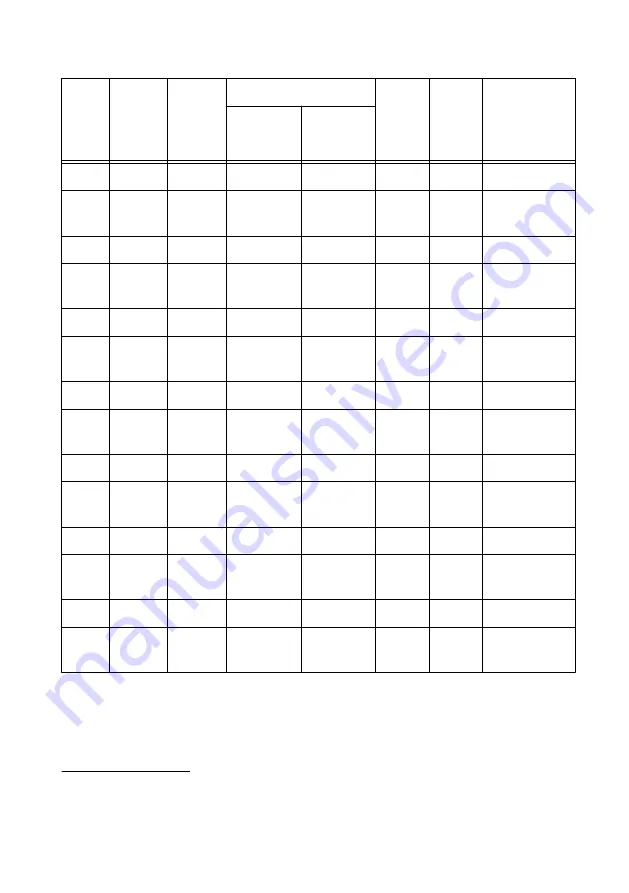
background image

Table 6.  1 M

Ω 

Bandwidth Verification

Config

Sample

Rate
(S/s)

Vertical

Range

(V

pk-pk

)

Test Point

As-

Found

Limits

(dB)

As-Left

Limits

(dB)

Measurement

Uncertainty

(dB)

4

Frequency

(MHz)

Amplitude

(dBm)


1

125 M

0.2

0.05

-13

2

250 M

0.2

98.1

-13

-3.0 to

1.0

-2.5 to

0.9

±0.134

3

125 M

0.7

0.05

-2.1

4

250 M

0.7

98.1

-2.1

-3.0 to

1.0

-2.5 to

0.9

±0.133

5

125 M

1.4

0.05

3.9

6

250 M

1.4

98.1

3.9

-3.0 to

1.0

-2.5 to

0.9

±0.134

7

125 M

5

0.05

9

8

250 M

5

98.1

9

-3.0 to

1.0

-2.5 to

0.9

±0.133

9

125 M

10

0.05

9

10

250 M

10

98.1

9

-3.0 to

1.0

-2.5 to

0.9

±0.134

11

125 M

40

0.05

9

12

250 M

40

98.1

9

-3.0 to

1.0

-2.5 to

0.9

±0.134

13

125 M

80

0.05

9

14

250 M

80

98.1

9

-3.0 to

1.0

-2.5 to

0.9

±0.134

4

Measurement uncertainty is based on the following equipment and conditions:

Rohde & Schwarz NRP-Z91 at 20 °C to 25 °C.

Harmonics from the signal generator are less than -30 dBc.

26

  | 

ni.com

  | 

PXIe-5172 Calibration Procedure

Summary of Contents for PXIe-5172

Page 1: ...ew 7 Test System Characterization 8 Zeroing the Power Sensor 8 Characterizing Power Splitter Amplitude Balance and Loss 8 Verification 12 Verifying DC Accuracy 13 Verifying AC Amplitude Accuracy 17 Verifying 50 Ω Bandwidth 21 Verifying 1 MΩ Bandwidth 25 Verifying Timebase Accuracy 30 Verifying RMS Noise 31 Adjustment 33 Adjusting the PXIe 5172 33 Adjusting 1 MΩ Compensation Attenuator 34 Adjusting...

Page 2: ... later The PXIe 5172 was first supported in LabVIEW Instrument Design Libraries for Reconfigurable Oscilloscopes 16 2 You can download all required software from ni com downloads Related Documentation For additional information refer to the following documents as you perform the calibration procedure PXIe 5172 Getting Started Guide NI High Speed Digitizers Help PXIe 5172 Specifications NI Reconfig...

Page 3: ...al to ground 0 V Frequency 500 Hz Abberations 2 of peak for the first 500 ns DC generation Amplitude 5 V into 50 Ω 40 V into 1 MΩ Accuracy 0 025 of output 25 µV DMM NI PXI 4071 Verifications AC amplitude accuracy AC voltage measurement Range 0 1 Vpk pk to 20 Vpk pk Input impedance 10 MΩ Bandwidth 50 kHz Accuracy at 50 kHz 0 07 of reading 14 µV for 0 1 Vpk pk test point 0 06 of reading 71 µV for 0 ...

Page 4: ...requency 50 kHz SMB plug to BNC f adapter Fairview Microwave SM3633 Verifications Timebase accuracy DC accuracy Adjustment Frequency DC to 89 MHz Impedance 50 Ω SMA Tee f f f Fairview Microwave SM4942 Verifications AC amplitude accuracy Impedance 50 Ω Double banana plug to BNC f Pasternack PE9008 Verifications AC amplitude accuracy Impedance 50 Ω BNC m to SMA m cable x2 Fairview Microwave FMC02083...

Page 5: ...ne wave generation Amplitude 10 dBm to 16 dBm Frequency 50 kHz to 101 MHz Harmonics 30 dBc Power splitter Aeroflex Weinschel 1593 Test system characterization Verifications Bandwidth Amplitude 16 dBm to 16 dBm Frequency 50 kHz to 101 MHz VSWR 1 09 50 Ω SMA terminator m Fairview Microwave ST1819 Test system characterization Amplitude 10 dBm Frequency DC to 101 MHz VSWR 1 1 50 Ω SMB terminator plug ...

Page 6: ...dth Amplitude 10 dBm Frequency 50 kHz to 100 MHz VSWR 1 1 at 100 MHz Impedance 50 Ω Test Conditions The following setup and environmental conditions are required to ensure the PXIe 5172 meets published specifications Allow all test instruments a warm up time of at least the stated amount of time in their specifications document The warm up time ensures that the test instruments are at a stable ope...

Page 7: ... 5172 NI uses these limits to determine whether the PXIe 5172 meets the specifications when it is received for calibration Use the as found limits during initial verification The as left calibration limits are equal to the published NI specifications for the PXIe 5172 less guard bands for measurement uncertainty temperature drift and drift over time NI uses these limits to reduce the probability t...

Page 8: ...n The connectors on the device under test DUT and test equipment are fragile Perform the steps in these procedures with great care to prevent damaging any DUTs or test equipment Zeroing the Power Sensor 1 Ensure that the power sensor is not connected to any signals 2 Zero the power sensor using the built in function according to the power sensor documentation Characterizing Power Splitter Amplitud...

Page 9: ... the other power splitter output as splitter output 2 7 Connect the power sensor to splitter output 2 The following figure illustrates the hardware setup Figure 1 Connection Diagram for Measuring at Splitter 2 1 5 4 3 6 7 2 1 Signal generator 2 SMA f to N m adapter 3 SMA m to SMA m cable 4 50 Ω SMA terminator m 5 Power splitter 6 SMA m to N f adapter 7 Power sensor 8 Configure the power sensor wit...

Page 10: ... settling 12 Use the power sensor to measure the power in dBm 13 Repeat steps 9 through 12 for each configuration in the Power Splitter Characterization table recording each result as splitter output 2 power where each configuration has a corresponding value 14 Disconnect the power sensor and 50 Ω SMA terminator m from splitter output 2 and splitter output 1 15 Connect the power sensor to splitter...

Page 11: ... for the Test Point Frequency value using the power sensor frequency correction function 19 Wait 0 1 second for settling 20 Use the power sensor to measure the power in dBm 21 Repeat steps 17 through 20 for each configuration in the Power Splitter Characterization table recording each result as splitter output 1 power where each configuration has a corresponding value 22 Calculate the splitter bal...

Page 12: ...he performance verification procedures assume that adequate traceable uncertainties are available for the calibration references Verification of the PXIe 5172 is complete only after you have successfully completed all tests in this section using the As Found Limits Refer to the following figure for the names and locations of the PXIe 5172 front panel connectors You can find information about the f...

Page 13: ... CH 2 CH 3 CH 4 CH 5 CH 5 CH 7 Verifying DC Accuracy This procedure verifies the DC accuracy of the PXIe 5172 by comparing the voltage measured by the device to the value sourced by the voltage standard Caution Avoid touching the connections when generating a high voltage from the calibrator Refer to the following table as you complete the following steps PXIe 5172 Calibration Procedure National I...

Page 14: ... 0 5 1 130 5 94 3 11 0 39 12 50 1 4 0 5 1 130 5 94 3 11 0 39 13 50 5 0 2 250 13 0 6 33 0 74 14 50 5 0 2 250 13 0 6 33 0 74 15 50 5 2 5 4 750 23 0 11 6 1 55 16 50 5 2 5 4 750 23 0 11 6 1 55 17 50 10 0 4 500 25 7 12 6 1 62 18 50 10 0 4 500 25 7 12 6 1 62 19 1 M 0 2 0 0 090 0 91 0 49 0 049 20 1 M 0 2 0 0 090 0 91 0 49 0 049 21 1 M 0 2 0 5 0 590 2 91 1 54 0 15 1 Measurement uncertainty based on Fluke ...

Page 15: ... 5 0 2 250 13 0 6 50 0 74 33 1 M 5 4 5 6 750 31 0 16 0 1 64 34 1 M 5 4 5 6 750 31 0 16 0 1 64 35 1 M 10 0 4 500 25 7 13 0 1 62 36 1 M 10 0 4 500 25 7 13 0 1 62 37 1 M 10 4 5 9 000 43 7 22 5 2 85 38 1 M 10 4 5 9 000 43 7 22 5 2 85 39 1 M 40 0 18 00 101 4 42 8 6 48 40 1 M 40 0 18 00 101 4 42 8 6 48 41 1 M 40 20 38 00 201 4 91 8 14 8 42 1 M 40 20 38 00 201 4 91 8 14 8 1 Measurement uncertainty based ...

Page 16: ...nfigure the calibrator to output the Test Point value from the DC Accuracy Verification table 5 Enable the calibrator output 6 Wait one second for settling then record the measured voltage 7 Use the following formula to calculate the voltage error DC voltage error Vmeasured Test Point 8 Compare the voltage error to the appropriate limit from the DC Accuracy Verification table 9 Repeat steps 2 thro...

Page 17: ...alibrator output 19 Connect the calibrator test head to channel 5 of the PXIe 5172 using an SMB plug to BNC f and repeat steps 2 through 8 for each configuration listed in the DC Accuracy Verification table 20 Disable the calibrator output 21 Connect the calibrator test head to channel 6 of the PXIe 5172 using an SMB plug to BNC f and repeat steps 2 through 8 for each configuration listed in the D...

Page 18: ...15 0 10 0 013 5 50 10 5 5 00 0 15 0 10 0 017 6 1 M 0 2 0 1 0 05 0 15 0 10 0 018 7 1 M 0 7 0 35 0 50 0 15 0 10 0 011 8 1 M 1 4 0 7 0 50 0 15 0 10 0 014 9 1 M 5 2 5 5 0 0 15 0 10 0 013 10 1 M 10 5 5 0 0 15 0 10 0 017 11 1 M 40 20 50 0 0 25 0 18 0 048 12 1 M 80 20 50 0 0 25 0 18 0 048 2 Measurement Uncertainty is based on the following equipment and conditions NI PXI 4071 specifications apply after s...

Page 19: ...to channel 0 of the PXIe 5172 as shown in the AC Verification Test Connections figure 2 Configure the DMM with the following settings Function AC voltage Resolution 6 5 digits Min frequency 49 kHz Auto Zero Enabled Range the DMM Range value from the AC Amplitude Accuracy Verification table 3 Configure the PXIe 5172 with the following settings Input impedance the Input Impedance value from the AC A...

Page 20: ...pare the amplitude error to the appropriate Limit from the AC Amplitude Accuracy Verification table 10 Repeat steps 2 through 9 for each configuration listed in the AC Amplitude Accuracy Verification table 11 Disable the function generator output 12 Connect the DMM and function generator to channel 1 of the PXIe 5172 as shown in the AC Verification Test Connections figure and repeat steps 2 throug...

Page 21: ...rification Test Connections figure and repeat steps 2 through 9 for each configuration listed in the AC Amplitude Accuracy Verification table 25 Disable the function generator output Verifying 50 Ω Bandwidth Follow this procedure to verify the 50 Ω analog bandwidth of the PXIe 5172 by generating a sine wave and comparing the amplitude measured by the PXIe 5172 to the amplitude measured by the powe...

Page 22: ...wer sensor assembly from the Test System Characterization section to channel 0 of the PXIe 5172 using an SMB plug to SMB m adapter Note The power sensor assembly must match the configuration used in the Test System Characterization section in which the power sensor is connected to splitter output 1 and the signal generator is connected to the input port of the power splitter The following figure i...

Page 23: ...nsor 2 SMA m to N f adapter 3 SMA m to SMB plug adapter 4 Power splitter 5 PXIe 5172 6 SMA m to SMA m cable 7 SMA f to N m adapter 8 Signal generator 2 Configure the power sensor with the following settings Power measurement continuous average Path selection automatic Averaging automatic Averaging resolution 4 0 001 dB Aperture 20 ms PXIe 5172 Calibration Procedure National Instruments 23 ...

Page 24: ...easured input power 8 Calculate the corrected input power using the following equation corrected input power measured input power splitter balance Note Select the splitter balance value from the list of test points from the Test System Characterization section for the current Test Point Frequency 9 Use the PXIe 5172 to acquire and measure the power using the Extract Single Tone Information VI conv...

Page 25: ...idth Verification table 24 Disable the signal generator output 25 Connect splitter output 2 of the power sensor assembly to channel 5 of the PXIe 5172 and repeat steps 3 through 14 for each configuration listed in the 50 Ω Bandwidth Verification table 26 Disable the signal generator output 27 Connect splitter output 2 of the power sensor assembly to channel 6 of the PXIe 5172 and repeat steps 3 th...

Page 26: ...1 4 0 05 3 9 6 250 M 1 4 98 1 3 9 3 0 to 1 0 2 5 to 0 9 0 134 7 125 M 5 0 05 9 8 250 M 5 98 1 9 3 0 to 1 0 2 5 to 0 9 0 133 9 125 M 10 0 05 9 10 250 M 10 98 1 9 3 0 to 1 0 2 5 to 0 9 0 134 11 125 M 40 0 05 9 12 250 M 40 98 1 9 3 0 to 1 0 2 5 to 0 9 0 134 13 125 M 80 0 05 9 14 250 M 80 98 1 9 3 0 to 1 0 2 5 to 0 9 0 134 4 Measurement uncertainty is based on the following equipment and conditions Ro...

Page 27: ...racterization section to channel 0 of the PXIe 5172 Note The power sensor assembly must match the configuration used in the Test System Characterization section in which the power sensor is connected to splitter output 1 and the signal generator is connected to the input port of the power splitter The following figure illustrates the hardware setup PXIe 5172 Calibration Procedure National Instrume...

Page 28: ... 2 3 1 Power sensor 2 SMA m to N f adapter 3 SMA m to SMB plug adapter 4 Power splitter 5 50 Ω SMA feed thru terminator 6 PXIe 5172 7 SMA m to SMA m cable 8 SMA f to N m adapter 9 Signal generator 2 Configure the power sensor with the following settings Power measurement Continuous average Path selection automatic Averaging automatic 28 ni com PXIe 5172 Calibration Procedure ...

Page 29: ...Calculate the corrected input power using the following equation corrected input power measured input power splitter balance Note Select the splitter balance value from the list of test points from the Test System Characterization section for the current Test Point Frequency 9 Use the PXIe 5172 to acquire and measure the power using the Extract Single Tone Information VI converting the result from...

Page 30: ...tion Table 24 Disable the signal generator output 25 Connect splitter output 2 of the power sensor assembly from the Test System Characterization section to channel 5 of the PXIe 5172 Repeat steps 3 through 14 for each configuration in the 1 MΩ Bandwidth Verification Table 26 Disable the signal generator output 27 Connect splitter output 2 of the power sensor assembly from the Test System Characte...

Page 31: ...rror using the following formula Timebase error Fmeasured 89 106 89 7 Compare the timebase error to the appropriate limit from the Timebase Accuracy Verification table Note Timebase verification is only required on one channel 8 Disable the calibrator output Verifying RMS Noise Follow this procedure to verify the RMS noise of the PXIe 5172 using a 50 Ω terminator Table 8 RMS Noise Verification Con...

Page 32: ...the acquired waveform Use the standard deviation to compute the RMS noise using the following formula RMS noise of FS 100 σ Vertical range where σ is the standard deviation of the acquired waveform 4 Compare the RMS noise to the appropriate Limit from the RMS Noise Verification table 5 Repeat steps 2 through 4 for each configuration listed in the RMS Noise Verification table 6 Connect the 50 Ω SMB...

Page 33: ...erence procedure on channel 0 5 Complete the Adjusting Timebase procedure on channel 0 This procedure only needs to run on one channel 6 Complete the Adjusting the 1 MΩ Compensation Attenuator procedure on channel 1 7 Complete the Adjusting the 1 MΩ DC Reference procedure on channel 1 8 Complete the Adjusting 50 Ω DC Reference procedure on channel 1 9 Complete the Adjusting the 1 MΩ Compensation A...

Page 34: ... close the NI SCOPE session Adjusting 1 MΩ Compensation Attenuator Follow this procedure to adjust the 1 MΩ compensation attenuator of the PXIe 5172 1 Connect the calibrator test head to the specified channel of the PXIe 5172 using an SMB plug to BNC f adapter 2 Call the niHsai Group A External Cal API v1 Host lvclass Compensated Attenuator Cal Initialize VI with the following settings channel The...

Page 35: ... Wait 1 second for settling 6 Call the niHsai Group A External Cal API v1 Host lvclass DC Reference Cal Adjust VI with the following settings actual voltage generated V The DC voltage present on the specified channel of the PXIe 5172 7 Repeat steps 3 through 6 until the DC cal complete indicator from the niHsai Group A External Cal API v1 Host lvclass DC Reference Cal Adjust VI returns TRUE 8 Disa...

Page 36: ...1 Host lvclass Timebase Cal Initialize VI with the following settings channel The specified channel 3 Call the niHsai Group A External Cal API v1 Host lvclass Timebase Cal Configure VI to obtain the frequency to generate and configure the calibrator to output a 1 25 Vpk pk sine wave at the specified frequency into 50 Ω 4 Enable the calibrator output if not already enabled 5 Wait 1 second for settl...

Page 37: ...ty and other services Visit ni com register to register your NI product Product registration facilitates technical support and ensures that you receive important information updates from NI A Declaration of Conformity DoC is our claim of compliance with the Council of the European Communities using the manufacturer s declaration of conformity This system affords the user protection for electromagn...

Page 38: ...ents EULAs and third party legal notices in the readme file for your NI product Refer to the Export Compliance Information at ni com legal export compliance for the NI global trade compliance policy and how to obtain relevant HTS codes ECCNs and other import export data NI MAKES NO EXPRESS OR IMPLIED WARRANTIES AS TO THE ACCURACY OF THE INFORMATION CONTAINED HEREIN AND SHALL NOT BE LIABLE FOR ANY ...

Reviews: